Table of Contents
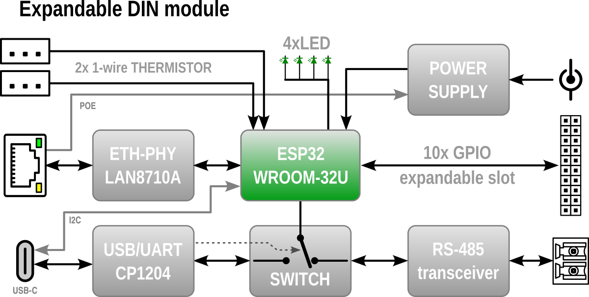
Expandable DIN module


Main features
- Ethernet conectivity
- RS-485 or USB-C interface (share same serial and baudrate speed)
- Direct connection of TWO 1-wire thermistor DS18B20
- 11 GPIOs
- Mounting on DIN rail
- Expandable
- Arduino firmware
- Block diagram


Quick start guide
- Connect to the power or USB-C
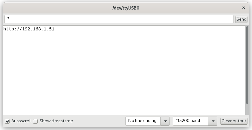
- Connect a serial console (115200 baud) to USB-C where you ask to IP address assigned from DHCP with press ? and enter.
- Now you can configure the device via the web interface.


Arduino firmware
Precompiled .bin
- is available on GitHub release page (without label ESPhome).
Compile
The code is created for Arduino IDE and is compilable with these fixed settings
-
- just copy it to your /Arduino/libraries directory
- Specifically commit Arduino ESP32 libraries
cd ~/Arduino/hardware/espressif/esp32
git clone https://github.com/espressif/arduino-esp32.git
cd <repository-name>
git checkout c2c8d189928386c872aa6cd7ba7a87c8019c5663
- Firmware source available on GitHub
Upload
- At the top of the web page there is a link “Upload FW” under which the form for uploading the firmware is available
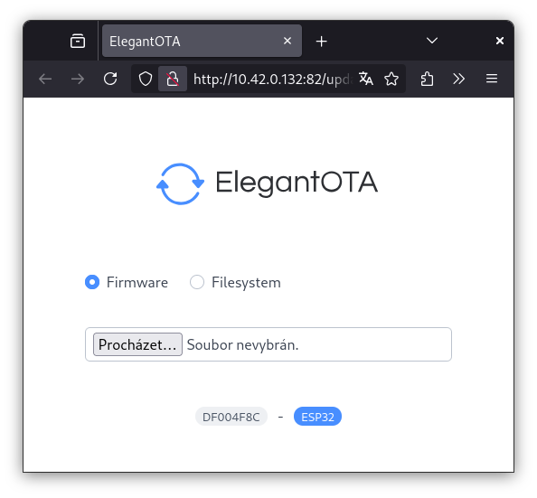
- or via USB-C using, for example, the web tool https://web.esphome.io/

Implemented functions
The firmware currently makes peripherals accessible to MQTT, but it can be used as a basis for programming your own functionalities, or using your own code.
- Connectors (T1 and T2) for connecting two DS18B20 digital thermistors with automatic detection. Reading temperature every 20 seconds and sending to MQTT with topic /T1-Celsius
- Ethernet connection using RJ45 connector with IP address retrieval from DHCP server. Static IP address setting is not implemented
- http web server publishing two pages
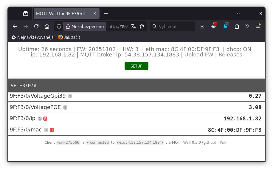
- mqtt-wall, which is a web MQTT client, for displaying messages that the device has sent to the MQTT broker
- SETUP page for configuring the device contains settings
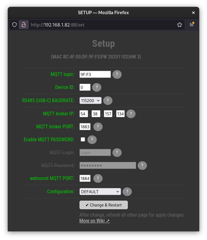
- MQTT topic
- Device ID
- RS485 (USB-C) BAUDRATE
- MQTT broker IP
- MQTT broker PORT
- websocet MQTT PORT
- MQTT Login
- MQTT Password
- Saving device settings to internal eeprom
- OTA update - allows you to update the device firmware via Ethernet via the web interface. Available at [IP]:82/update, or from the link on the main page of mqtt-wall
- MQTT client for sending and receiving messages from the broker
- Measuring POE voltage and sending the value to MQTT when it changes
- Watchdog timer, triggers a device restart if the firmware stops for longer than 60s
- detect USB-C plug and publish to MQTT with topic /USBdetect
- RS485-MQTT proxy - received RS485 data forward to MQTT with topic /RS485_RX

How to connect
Power
- The modul can be powered in the range of 9-14V DC with a maximum consumption of 0,5A
- The power supply can be connected in two ways
- pluggable DC jack directly.
Attention to polarity!
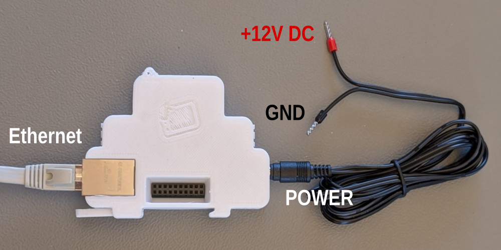
This input is protected by a 1A fuse.
- Ethernet passive POE with external POE injector
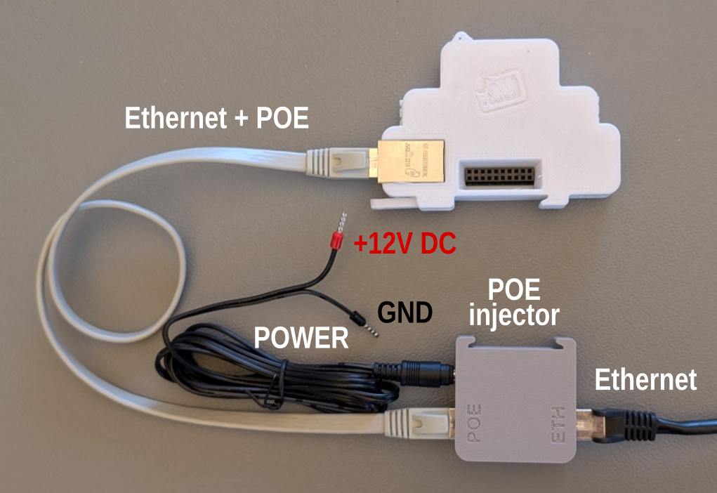
The POE injector is protected with also 0.5A fuse.


Interfaces pinout
| Functionality | Front view | pinout |
| Power |  | 1 - 11-13.8V / 1A max DC PWR input 2 - GND |
| 2x 1-wire thermistor |  | 2x JST 1-wire for DS18B20 thesrnistor 1 - +3,3V / max 500mA 2 - 1-wire bus (Gpio15) 3 - GND |
| RS-485 |  | 2 - RS485-A 1 - RS485-B |
| Four LEDs | RED - fail fuse GRN - ETH 100M GRN - ETH ACT GRN - Power |
|
| USB-C |  | USB-C serial +5V VBUS SBU1 - 3V3 Gpio33 (I2C SDA) SBU2 - 3V3 Gpio32 (I2C SCL) |
| Ethernet |  | 1,2,3,6 - Ethernet 4+5 - POE DC power input 12-24V/max 1A, any polarity 7+8 - POE DC power input 12-24V/max 1A, any polarity Green LED - 100M Yelow LED - ACT |
| 11 GPIO expandable slot | 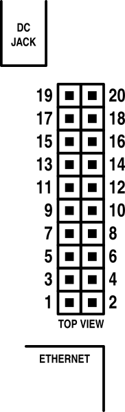 | GPIO 1 - +12V from DC jack or POE 2 - +12V from DC jack or POE 3 - GND 4 - GND 5 - GPIO5 6 - +3,3V from internal step down 7 - GPIO33 8 - GPIO15 9 - GPIO12 10 - GPIO14 11 - GPIO02 12 - GPIO13 13 - GPIO04 14 - GPIO0 15 - GPIO39 16 - GPIO16 17 - GPIO32 18 - GPIO36 19 - GND 20 - GND |
Source
Firmware
- GitHub Arduino sample code
- Releases on GitHub sign without ESPhome label
Hardware
- .PDF schematics rev 0.3
BOM
| 1x |  DC Power connector 5,5/2,1mm | https://www.tme.eu/cz/details/pc-2.1_5.5-14/konektory-dc/changzhou-dahua-imp-and-exp-group-co/vg18013a/ |
| 2x |  DS18B20 with JST conector | https://www.laskakit.cz/en/dallas-ds18b20-digitalni-vodotesne-cidlo-teploty-3m/ |
| 1x |  RS485 connector RS485 connector | https://www.tme.eu/cz/details/tj0231530000g/rozpojitelne-svorkovnice/amphenol-anytek/ |
| 2x |  M3x10mm M3x10mm | https://www.tme.eu/cz/details/b3x10_bn2844/srouby/bossard/1489380/ |
| 1x |  1A fuse 1A fuse | https://www.tme.eu/cz/details/0218001.txp/pojistky-5x20mm-zpozdene/littelfuse/ |
| 30g |  fillament PETG-V0 fillament PETG-V0 UL94-V0 UL certificate IEC 60695-11-10 | https://www.prusa3d.com/cs/produkt/prusament-petg-v0-natural-1kg/ |
| 1x | 3D print model | https://www.printables.com/model/1386414-arduino-esp32-ethernet-din-module |