din-wifi
This is an old revision of the document!
Table of Contents
WiFi DIN module


Main features
- WiFi or Ethernet conectivity
- RS-485 or USB-C interface (share same serial and baudrate speed)
- Direct connection of 1-wire thermistor DS18B20
- Three open collector outputs
- Mounting on DIN rail
- ESPhome firmware
BLOKOVE SCHEMA
Quick start guide
- Connect to the power or USB-C
- On your PC/notebook/phone select WiFi AP “EMS NG” and connect it
- Password is “12345678”
- open url http://192.168.4.1 and select your home WiFi AP and connect it
- After rebooting, connect a serial console (115200 baud) where you will see a connection to your home AP and an IP address assigned from DHCP. After connecting to this address, you can configure the device via the web interface…
- Asociate to Home assistant…
Update firmware
Precompiled firmware in .bin format
- is available on GitHub release page (with ESPhome label) in two variants. With activated WiFi or Ethernet interface - choose variant according to the interface you want to use.
- you can compile your own .bin file according to the configuration .yaml file also available on GitHub
You can upload the firmware in two ways
- via the web interface of your own device (integrated in ESPhome)
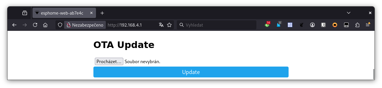
- via USB-C using, for example, the web tool https://web.esphome.io/

How to connect
Power
- The modul can be powered in the range of 12-24V DC with a maximum consumption of 1A
- The power supply can be connected in two ways
- pluggable two pin female terminal block.
Attention to polarity!
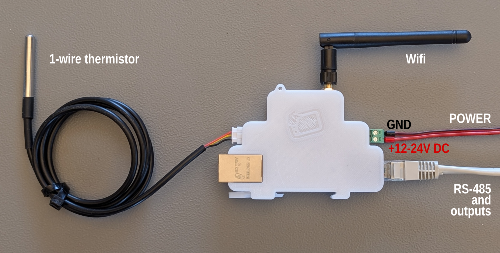
This input is protected by a 1A fuse.
- Ethernet passive POE with external POE injector
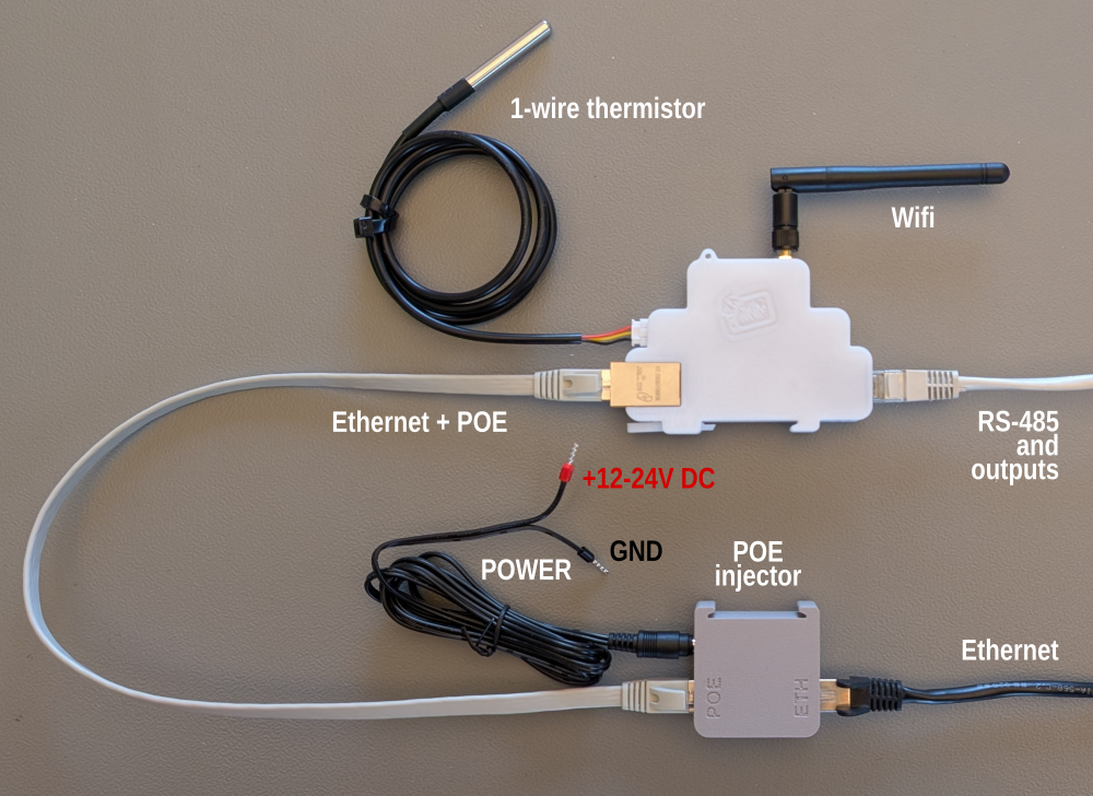
POE power is available even when the Ethernet interface is inactive and WiFi connectivity is used.
The POE injector is protected with a 0.5A fuse to prevent the current limit of the Ethernet isolation transformer from being exceeded.


Interfaces pinout
| Functionality | Front view | pinout |
| RS-485 Three open colector outputs |  | 1 - from 12 to 24V DC from PWR input 2 - open colector 500mA Stykac2 with 10k pull-up 3 - from 12 to 24V DC from PWR input 4 - open colector 500mA Stykac1 with 10k pull-up 5 - from 12 to 24V DC from PWR input 6 - open colector 500mA SSR with 10k pull-up 7 - RS485-A 8 - RS485-B Attention: because the USB-C interface shares the same serial UART with the RS-485 interface, RS-485 is not available after connecting USB. The USB-C connection is detected on GPIO36. For the same reason, both interfaces share the same Baudrate. |
| Power |  | 2 - input power from 12 to 24V DC/1A 1 - GND |
| WiFi |  | SMA female 2,4G WiFi antenna connector |
| Five LEDs | RED - fail fuse - To replace, it is necessary to open the module with an Allen key and replace the 1A fuse (see BOM) RED - SSR RED - STYKAC1 RED - STYKAC2 GREEN - Power |
|
| USB-C |  | USB-C serial +5V VBUS SBU1 - 3V3 Gpio33 (I2C SDA) SBU2 - 3V3 Gpio32 (I2C SCL) Attention: because the USB-C interface shares the same serial UART with the RS-485 interface, RS-485 is not available after connecting USB. The USB-C connection is detected on GPIO36. For the same reason, both interfaces share the same Baudrate. |
| 1-wire thermistor |  | JST 1-wire for DS18B20 thesrnistor 1 - +3,3V / max 500mA 2 - 1-wire bus (Gpio15) 3 - GND |
| Ethernet |  | 1,2,3,6 - Ethernet 4+5 - POE DC power input 12-24V/max 1A, any polarity 7+8 - POE DC power input 12-24V/max 1A, any polarity Green LED - 100M Yelow LED - ACT |
BOM
| 1x |  Power connector Power connector | https://www.tme.eu/cz/details/tj0231530000g/rozpojitelne-svorkovnice/amphenol-anytek/ |
| 1x |  DS18B20 with JST conector DS18B20 with JST conector | https://www.laskakit.cz/en/dallas-ds18b20-digitalni-vodotesne-cidlo-teploty-3m/ |
| 1x |  WiFi antenna + 5cm UF.L pigtail WiFi antenna + 5cm UF.L pigtail | https://www.hadex.cz/o856-antena-wifi-24ghz--pigtail-ufl-sma/?gQT=1 |
| 2x |  M3x10mm M3x10mm | https://www.tme.eu/cz/details/b3x10_bn2844/srouby/bossard/1489380/ |
| 1x |  1A fuse 1A fuse | https://www.tme.eu/cz/details/0218001.txp/pojistky-5x20mm-zpozdene/littelfuse/ |
| 30g |  fillament PETG-V0 fillament PETG-V0 UL94-V0 UL certificate IEC 60695-11-10 | https://www.prusa3d.com/cs/produkt/prusament-petg-v0-natural-1kg/ |
| 1x | 3D print model | https://www.printables.com/model/1386414-arduino-esp32-ethernet-din-module |
Firmware
on GitHub sign ESPhome label
Other
din-wifi.1764519891.txt.gz · Last modified: by ok1hra