This is an old revision of the document!
Table of Contents
IP switch 0.4c

Key features
- 16 ethernet controlled outputs with optional expandable board
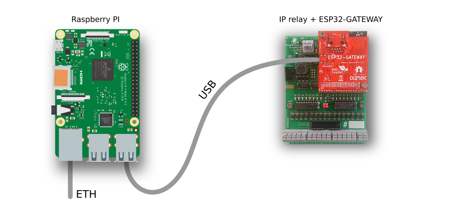
- Based on Olimex ESP32-GATEWAY ethernet module
- Configure open emitter or open colector outputs
- Simple “Wago” like terminal output connection
- 12-14V power (step down included)
- Optional color LCD display with touch screen support - not implemented
- Connect optional relay board with one flat cable
- Analog input optional connector
- DIN rail mount
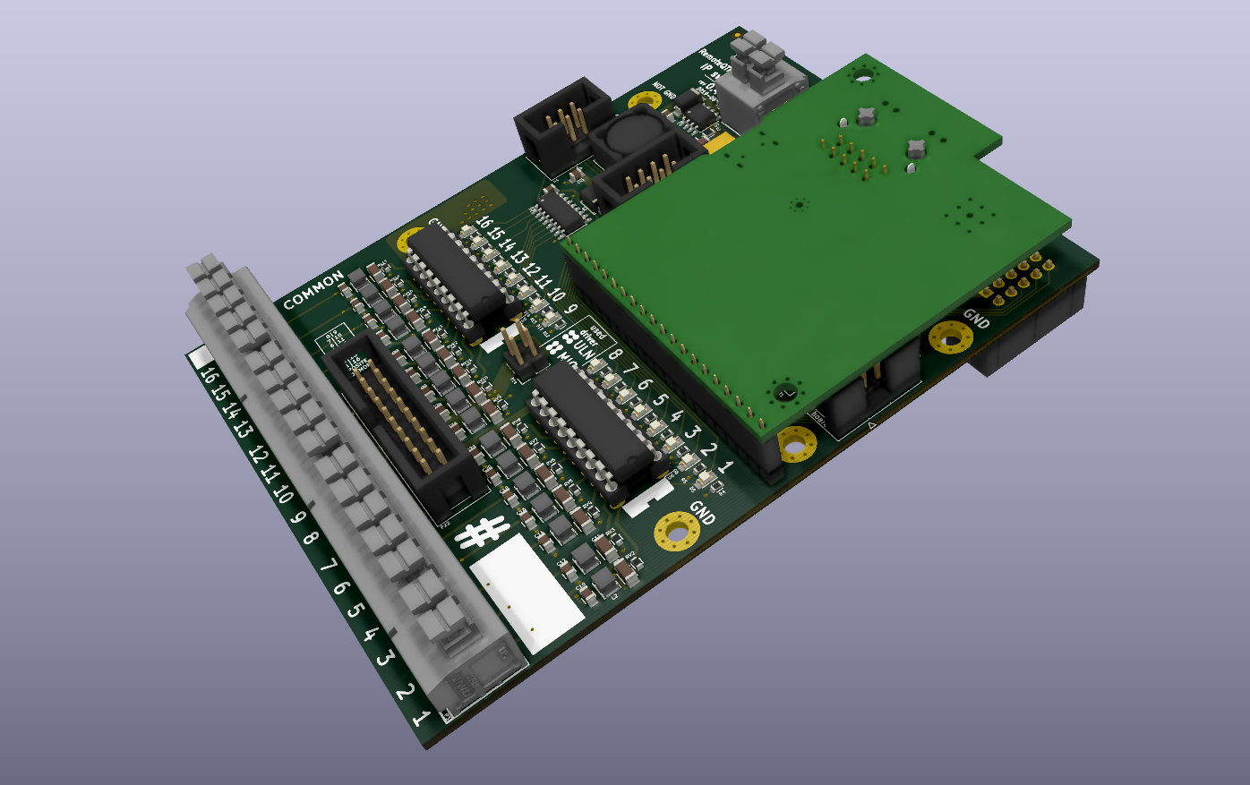
Hardware
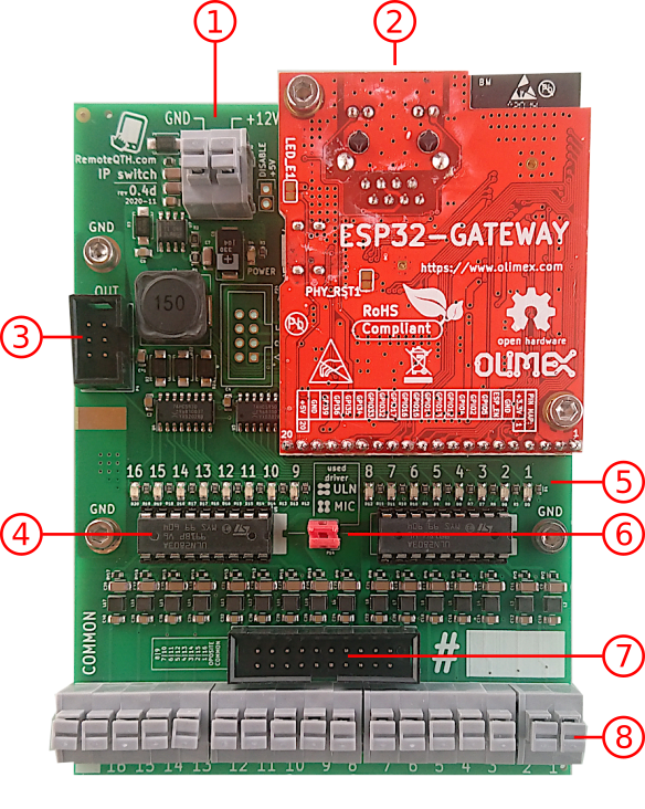
- Power supply (12-14V DC)
- Ethernet RJ45 connector
- Optional expand board connector
- Output driver with open collector or emiter
- LED light shown enabled output
- Two jumper for select output driver are used
- Connector for 16 relay board connected wth flat cable
- 16 output and common terminal (50V/500mA MAX) use for
- relay power if use open colector ULN driver
- relay GND if use open colector MIC driver
Sources
Firmware upload
- Install Arduino IDE
- Install ESP32 support from GitHub
- prefered via board manager
- Download firmware from GitGub
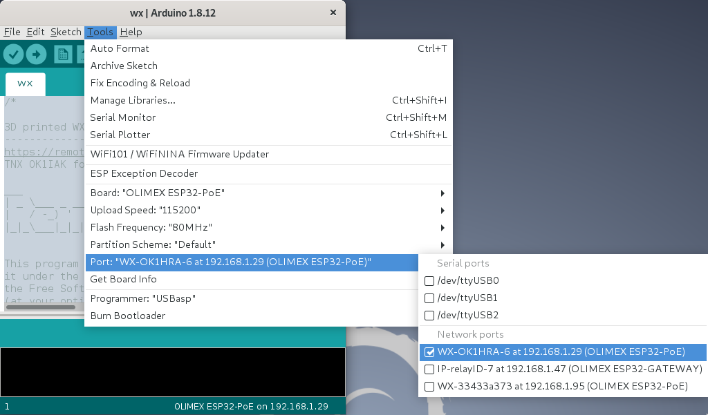
- Select menu Tools/Board:“OLIMEX ESP32-GATEWAY”
- Connect micro USB between ESP32-GATEWAY and PC
- Select menu Tools/Port/YOUR-CONNECTED-PORT
- Upload firmware
- After firmware upload you can upload next version of the firmware via IP, if you computer in same network. In Arduino IDE shows another choice Network ports
- password for OTA upload is remoteqth

Configure CLI
First step need get IP addres and telnet acces key
- After first upload firmware via USB, open serial monitor in Arduino IDE (Ctrl+Shift+M) and set
- baudrate to 115200
- No Line ending
- write ? and press enter show settings Command line interface
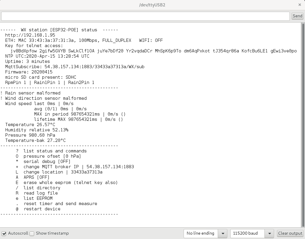
- copy and save
- IP address
- Key for telnet access (100 characters)

Second step connect remotely via IP
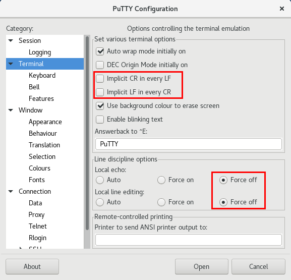
- Download and install PuTTY
- In menu Terminal preset CR/LF and line discipline by picture
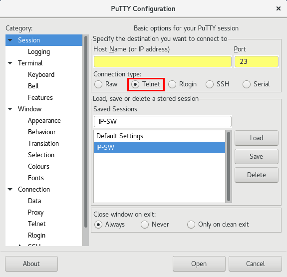
- In main menu Session select or set the following values

- select Telnet
- port 23
- write IP address (saved from first step acces)
- Sessions may be saved for next time
- for connect press Open
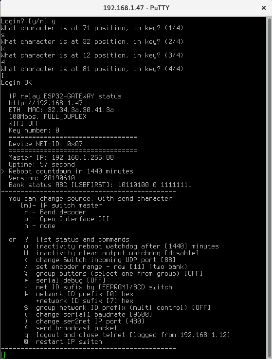
- Login confirm with press y
- Now answer four times the question of what character is on random selected position, in your key (key saved from first step acces)
- if you enter wrong three times, login will be blocked for next ten minutes
- After login your IP address store to EEPROM and next key will be required only if change your IP address
- Now logged in to CLI (command line interface) via telnet

- for Logout press q

CLI commands
CLI contains some commands for set or show information.
Commands for set source device
- m - Manual IP switch ← THIS USED
- r - Band decoder MK2
- o - Open Interface III
Other commands, RED is important
? - show status and help
w - set inactivity time in minutes, after them IP switch will be restarted (watchdog)
  before reboot store current output setting and restore after start
  zero value disable this watchdog
W - set inactivity time in minutes, after them IP switch will set all outputs to OFF
  if you need OFF all outputs after reboot watchdog, set smaller value than it
  zero value disable this watchdog
/ - set encoder range (2-g) for switching one from range % - enable/disable group buttons
  ! - SET group for each button separately
  : - List group buttons
  in one group may be activate only one output
  groups are free configurable
  the group can be any size 2-8 buttons
  there may be any buttons in the group, for example 1 and 8
  the number of groups is not limited
* - enable/disable serial debugging + - select get Network ID sufix from eeprom or hardware BCD switch # - set network ID
  Prefix (four high bit) in hexadecimal format (0-f)
      in standart mode prefix expanded range of network ID
      if enable Multi control, prefix disable, and use only on master device for his idetifications
  Sufix (four low bit) in hexadecimal format (0-f)
      settings available if sufix get from eeprom
      in standart mode sufix use for identification
      in Multi control mode define group ID (id for all shared devices)
$ - enable/disable Multi control function (sharing up to 16 master device) & - send broadcast packet for find control devices in local network . - if enable Multi control, show list detected IP switch by ID prefix @ - restart IP switch
How to assembly

What tools do you need to build
- Tin
- Solder
- Pliers
- Splitters
- + 2,5mm imbus (packed in KIT)
Steps of assembly
- Check all parts

- Solder pinsocket P17 to front side and pinheader P4 P14 P22

- Solder 20pin header to Olimex ESP32-GATEWAY front side

- Solder output terminal P6 P10 P11 P3

- Solder P2 input terminal

- Screw two M3x12mm spacers with lock nuts

- Insert four lock nuts, and two slim nuts to 3D printed DIN rail mount

- Screw with four screws M3x10mm

- Plug ESP32-GATEWAY to main board and screw with two screws M3x4mm

- Insert two output drivers and plug two jumpers in position dependency to used driver. Horizontal for ULN open colector, vertical for MIC open emiter