ip-switch
This is an old revision of the document!
Table of Contents
IP switch 0.4c
Key features
- 16 ethernet controlled outputs with optional expandable board
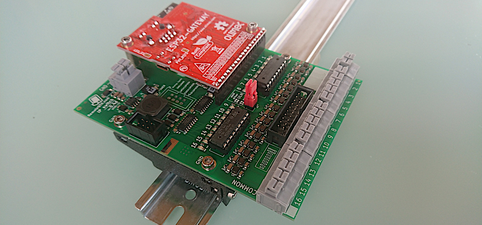
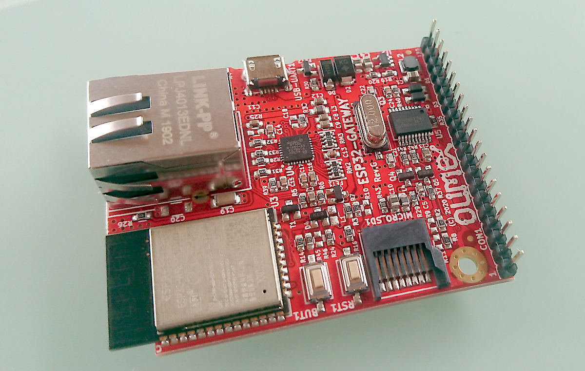
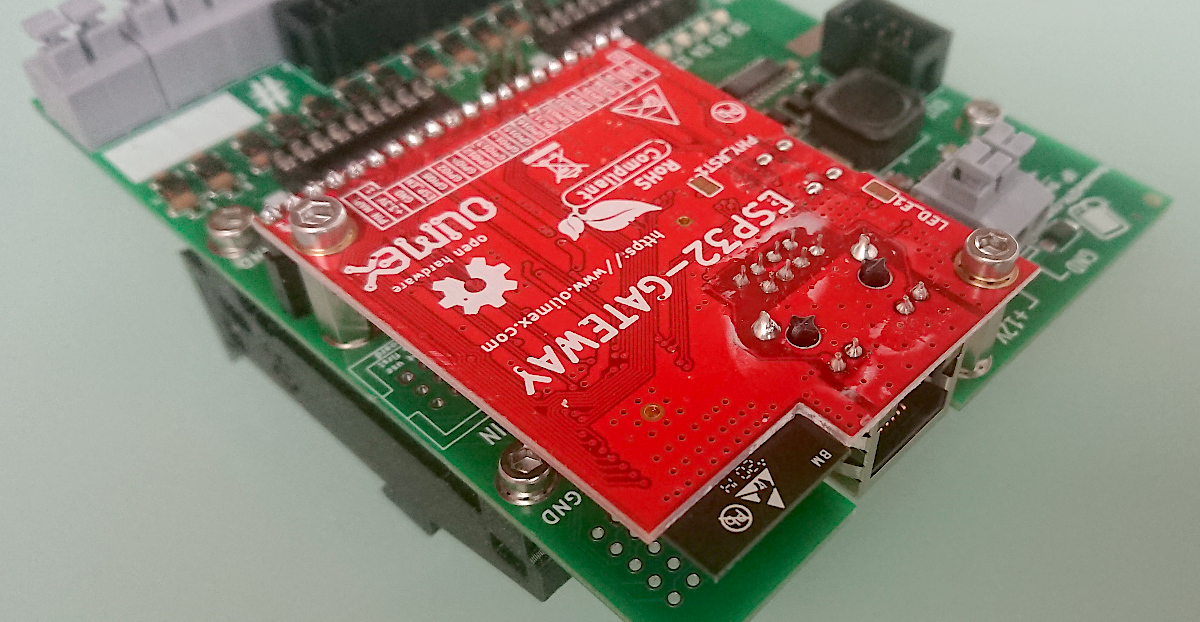
- Based on Olimex ESP32-GATEWAY ethernet module
- Configure open emitter or open colector outputs
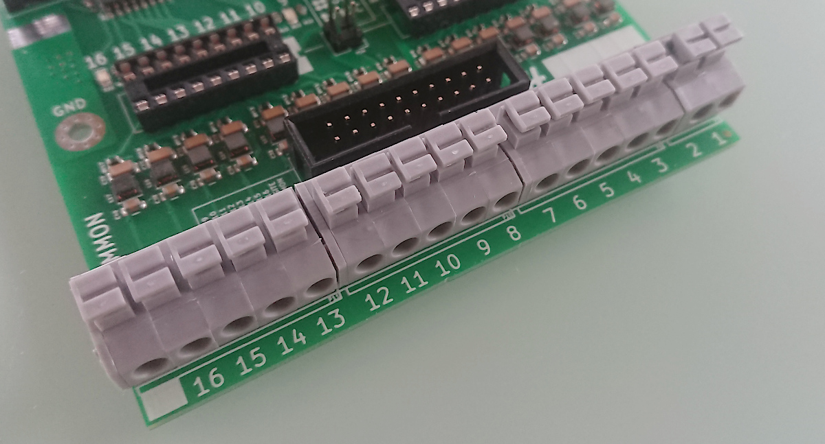
- Simple “Wago” like terminal output connection
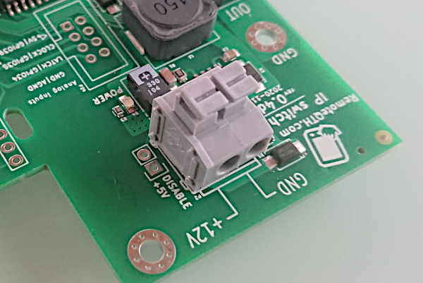
- 12-14V power (step down included)
- Optional color LCD display with touch screen support - not implemented
- Connect optional relay board with one flat cable
- Analog input optional connector
- DIN rail mount
Hardware
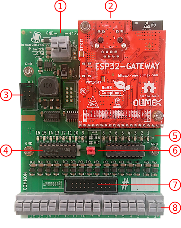
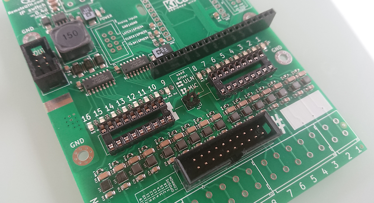
- Power supply (12-14V DC)
- Ethernet RJ45 connector
- Optional expand board connector
- Output driver with open collector or emiter
- LED light shown enabled output
- Two jumper for select output driver are used
- Connector for 16 relay board connected wth flat cable
- 16 output and common terminal (50V/500mA MAX) use for
- relay power if use open colector ULN driver
- relay GND if use open colector MIC driver
Sources
Firmware upload
- Install Arduino IDE
- Install ESP32 support from GitHub
- prefered via board manager
- Download firmware from GitGub
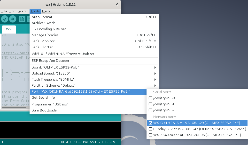
- Select menu Tools/Board:“OLIMEX ESP32-GATEWAY”
- Connect micro USB between ESP32-GATEWAY and PC
- Select menu Tools/Port/YOUR-CONNECTED-PORT
- Upload firmware
- password for OTA upload is remoteqth
Configure CLI
First step need get IP addres and telnet acces key
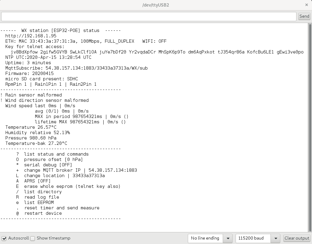
- After first upload firmware via USB, open serial monitor in Arduino IDE (Ctrl+Shift+M) and set
- baudrate to 115200
- No Line ending
- copy and save
- IP address
- Key for telnet access (100 characters)
Second step connect remotely via IP
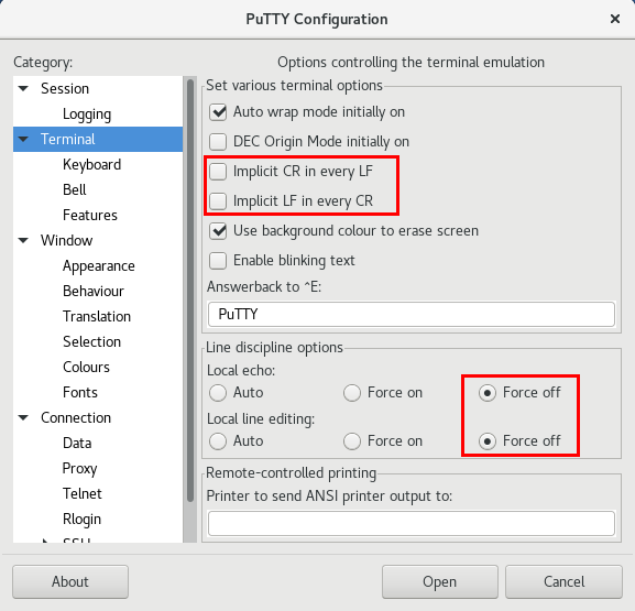
- Download and install PuTTY
-
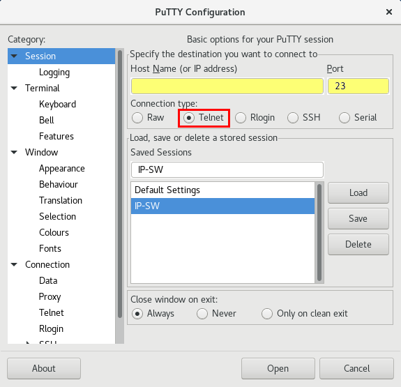
- select Telnet
- port 23
- write IP address (saved from first step acces)
- Sessions may be saved for next time
- for connect press Open
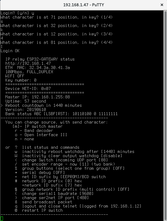
- Login confirm with press y
- Now answer four times the question of what character is on random selected position, in your key (key saved from first step acces)
- if you enter wrong three times, login will be blocked for next ten minutes
- After login your IP address store to EEPROM and next key will be required only if change your IP address
- for Logout press q
CLI commands
CLI contains some commands for set or show information.
Commands for set source device
- m - Manual IP switch ← THIS USED
- r - Band decoder MK2
- o - Open Interface III
Other commands, UPERCASE is important
- ? - show status and help
- w - set inactivity time in minutes, after them IP switch will be restarted (watchdog)
- before reboot store current output setting and restore after start
- zero value disable this watchdog
- W - set inactivity time in minutes, after them IP switch will set all outputs to OFF
- if you need OFF all outputs after reboot watchdog, set smaller value than it
- zero value disable this watchdog
- / - set ENCODER RANGE (2-g) for switching one from range
- % - enable/disable group buttons
- ! - set group for each button separately
- : - List group buttons
- in one group may be activate only one output
- groups are free configurable
- the group can be any size 2-8 buttons
- there may be any buttons in the group, for example 1 and 8
- the number of groups is not limited
- * - enable/disable serial debugging
- + - select get Network ID sufix from eeprom or hardware BCD switch
- # - set NETWORK ID
- Prefix (four high bit) in hexadecimal format (0-f)
- in standart mode prefix expanded range of network ID
- if enable Multi control, prefix disable, and use only on master device for his idetifications
- Sufix (four low bit) in hexadecimal format (0-f)
- settings available if sufix get from eeprom
- in standart mode sufix use for identification
- in Multi control mode define group ID (id for all shared devices)
- $ - enable/DISABLE MULTI CONTROL function (sharing up to 16 master device)
- & - send broadcast packet for find control devices in local network
- . - if enable Multi control, show list detected IP switch by ID prefix
- @ - restart IP switch
For controlled from Manual IP switch
- Upload firmware by previous steps
- Set encoder range via CLI with command n
- Set source via CLI or web interface to m
- Set network ID prefix same on both devices via CLI in range 0-7
- Select Network ID sufix same on both devices via CLI in range ID 0-7
- Connect to same local network with DHCP as Manual IP switch
- After power up both devices, is automaticaly pair
Web status page
How IP addres got the device from the DHCP server?
- show in serial terminal after reboot, or send ? character
- or find some network scanner
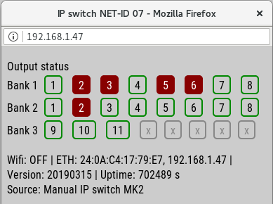
Show all outputs status
- Parameter of WiFi or ethrnet IP connect
- Firmware version
- Device uptime
- How source controled his
- Notice - show this page can extend reaction latency IP switch
How to assembly
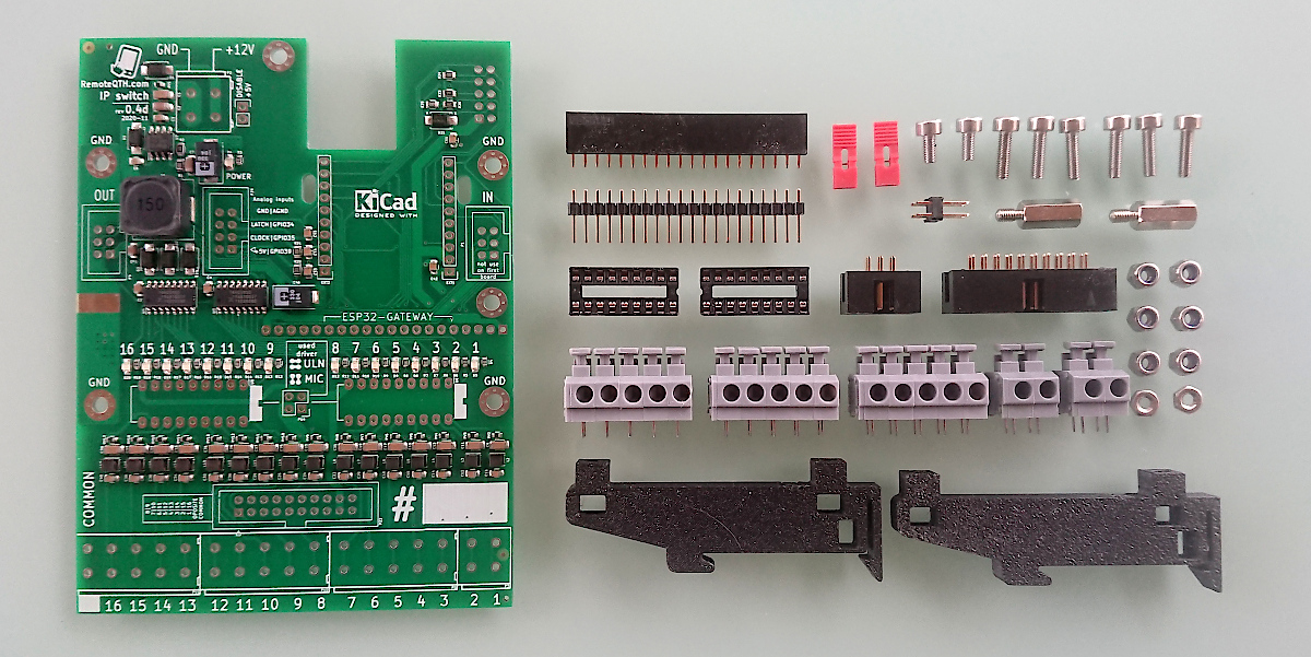
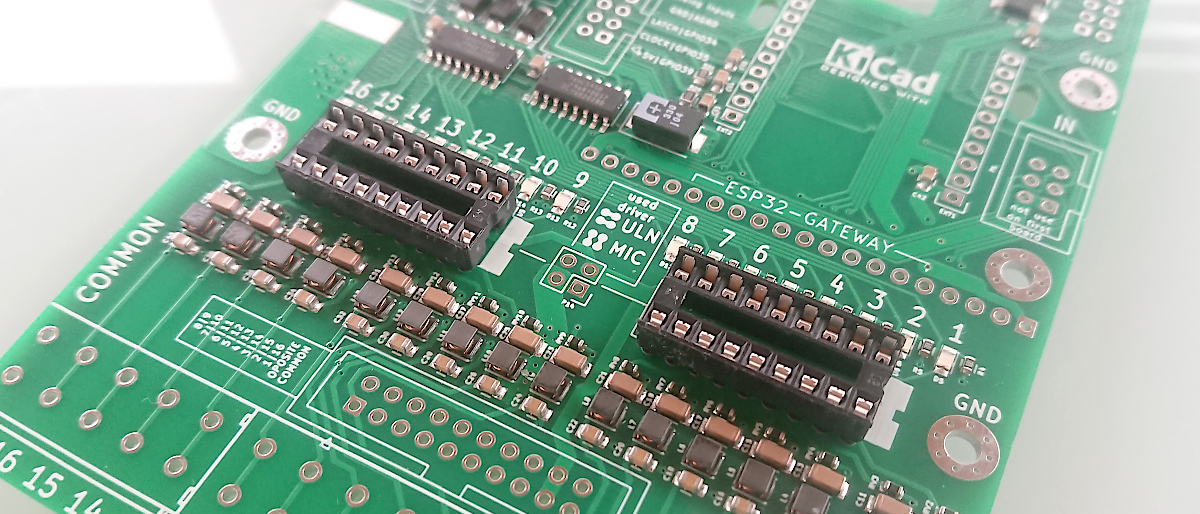
Steps of assembly
ip-switch.1607629378.txt.gz · Last modified: by ok1hra

