This is very simply preamplifier module with 2N5109 transistor based on W7IUV design. You can use it as high IP preamplifier, buffer amplifier or small driver. Gain is up to 18dB and there is also build in variable ATT. You can easy set gain as high as you need! As well you can set right transistor bias with multi turn potentiometer. Two relays offer bypass switching if there is no power supply.

======Quick Start Guide======
*[Applications|https://remoteqth.com/wiki/index.php?page=RX+-+Preamp+module+2N5109#Applications]
*[KIT|https://remoteqth.com/wiki/index.php?page=RX+-+Preamp+module+2N5109#KIT]
*[Parameters|https://remoteqth.com/wiki/index.php?page=RX+-+Preamp+module+2N5109#Parameters]
*[Schematic|https://remoteqth.com/wiki/index.php?page=RX+-+Preamp+module+2N5109#Schematic]
*[Part list|https://remoteqth.com/wiki/index.php?page=RX+-+Preamp+module+2N5109#Part_List]
*[Board|https://remoteqth.com/wiki/index.php?page=RX+-+Preamp+module+2N5109#Board]
*[KIT Assembling|https://remoteqth.com/wiki/index.php?page=RX+-+Preamp+module+2N5109#KIT_Assembling]
*[Tunning|https://remoteqth.com/wiki/index.php?page=RX+-+Preamp+module+2N5109#Tunning]
*[Article from W7IUV|https://remoteqth.com/wiki/index.php?page=RX+-+Preamp+module+2N5109#Doc]
Applications
* High IP RX preamplifier - RX antennas * Buffer amplifier * Driver amplifier
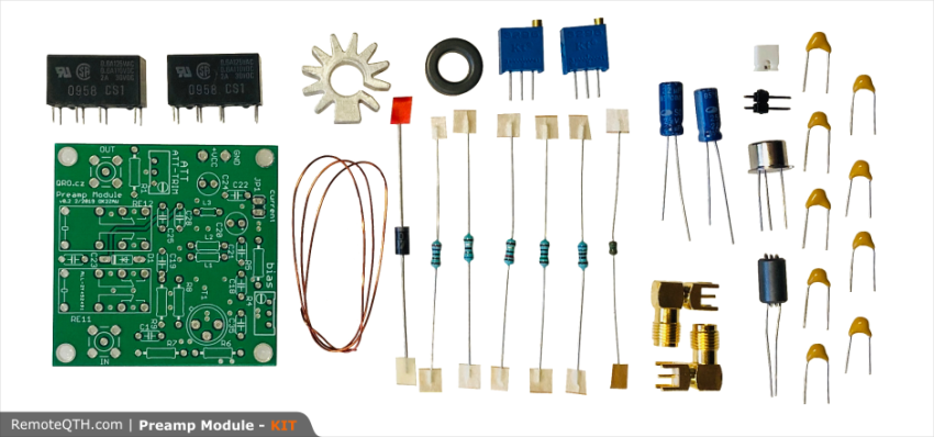
KIT
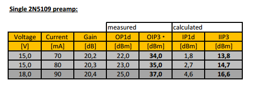
Parameters
* Supply voltage 12 to 14 V - HIGHER SUPPLY VOLTAGE NEEDS COOLING AND RESISTORS TO RELAYS!!!
* Supply current up to 180 mA - include relays current
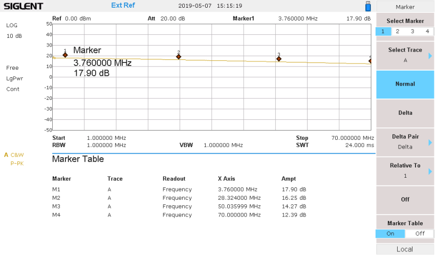
* gain for 50 kHz to 1 MHz

* gain for 1 MHz to 70 MHz
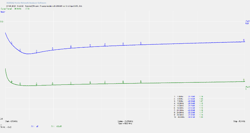
* Input SWR, S11
Schematic

Part List
| Part | Value | Device |
| ATT-TRIM | R 200R | R-TRIMM64W Multi turns Bourns 3296 W |
| C1 | C 100nF | C-EU050-024×044 |
| C18 | C 100nF | C-EU050-024×044 |
| C19 | C 100nF | C-EU050-024×044 |
| C20 | CPOL 10uF/25V | CPOL-EUE2.5-5 |
| C21 | C 100nF | C-EU050-024×044 |
| C22 | C 100nF | C-EU050-024×044 |
| C23 | C 100nF | C-EU050-024×044 |
| C24 | CPOL 10uF/25V | CPOL-EUE2.5-5 |
| C25 | C 100nF | C-EU050-024×044 |
| C28 | C 100nF | C-EU050-024×044 |
| C35 | C 100nF | C-EU050-024×044 |
| D1 | D 1N4148 DO35-7 | 1N4148DO35-7 |
| IN | CON SMA | ST-SMB-V |
| JP1 | JUMPER | JP1E |
| L1 | T 5t | FT50-75 |
| L2 | T 5t | FT50-75 |
| L3 | FR3-FR TYPE | FR type |
| OUT | SMA | SMA F |
| R1 | R 150 | R-EU_0207/10 |
| R4 | R 2k | R-TRIMM64W |
| R5 | R 2k7 | R-EU_0207/10 |
| R6 | R 680 | R-EU_0207/10 |
| R7 | R 1k | R-EU_0207/10 |
| R8 | R 6R8 | R-EU_0207/10 |
| R9 | R 12R | R-EU_0207/10 |
| RE11 | G5V-2 | G5V-2 |
| RE12 | G5V-2 | G5V-2 |
| T1 | TR 2N5109 | Motorola |
| X1 | Wago | W237-102 |
!Board
[https://remoteqth.com/img/ZAW-WIKI/preampmodule/brd_v0.1.png}}
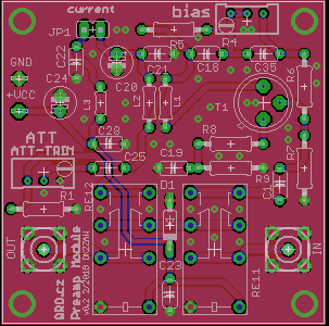
!KIT Assembling
* Insert two multi-turn trimmers
there is 2 kOhms (202) and 200 Ohm (201)
* Insert resistors
 * continue with capacitors
small yellow 104 apacitors are 100 nF
continue with two blue electrolytic capacitor - PLEASE be careful on polarity!
minus (-) is marked on capacitor, plus (+) on PCB
* continue with capacitors
small yellow 104 apacitors are 100 nF
continue with two blue electrolytic capacitor - PLEASE be careful on polarity!
minus (-) is marked on capacitor, plus (+) on PCB


 * Insert diode, relay and inductor
two Omron relays
Diode 1N4007 - please follow polarity on PCB
small inductor L3
* Insert diode, relay and inductor
two Omron relays
Diode 1N4007 - please follow polarity on PCB
small inductor L3


 * Insert transistor to the radiator and wind output transformer
use screw driver to open radiator a little bit if needed.
there is small ferrite core T50-75
wind 5 turns of bifilar wires
* Insert transistor to the radiator and wind output transformer
use screw driver to open radiator a little bit if needed.
there is small ferrite core T50-75
wind 5 turns of bifilar wires
 *Example of the binocular wires :)
 * please measure start and end of both windings
* insert it into the PCB in the right order!
* please measure start and end of both windings
* insert it into the PCB in the right order!


Tunning
* There is nothing to tune on RF side. It is wide band amplifier.
* You only need to set right TRANSISTOR BIAS current and Gain.
disconnect jumper JP1
connect mA meter there (200 mA scale is fine)
connect supply voltage you want - from 12 to 14 V
turn the resistor trimmer R4 (BIAS) and set bias current you want - it should be from 60 to 85 mA - depends on application
than connect jumper short back again
* With the resistor trimmer (ATT-TRIM) you can set amplifier gain as you need.
from 0 to about 18 dB
turn the ATT-TRIM (201)
Doc**
Article from W7UIV in PDF here