3d-print-rotator
Table of Contents
3D print rotator (revision 2023)
Source files on GitHub
Printables mirror
I include the source file in OpenScad and several preset exports, in dimensions S, M, MS, XL.
Size M is recommended, MS reduced for Prusa MK3 and MK4 printers. I also include the following data for each dimension:
- BOM
- Steel cover .DXF
- .STL files
- .3mf preset
It can be controlled via a web interface, using electronics Simple rotator interface V.


Torque test M size

Max torque 2200 kg/cm (215 N/m) without destroy
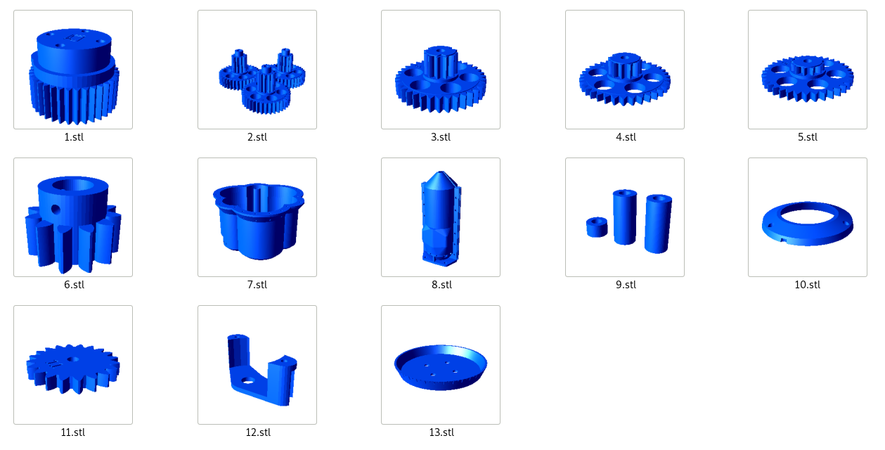
Printed parts
You can use 3D printing to order, for example at mirex3d.cz.
BOM
| | Printed parts Prefered black PETG filament | 13 pieces |
 | Top cover 4mm thick from stainless steel By .DXF file from GitHub depending on the size You can order online at idilna.cz | 1 piece |
 | M3 x 6mm, allen head, stainless steel | 3 pieces |
 | M3 x 10mm, allen head, stainless steel | 11 pieces |
 | M3 nuts, stainless steel | 8 pieces |
 | M4 x 16 mm, allen head, stainless steel | 32 pieces |
 | M4 nuts, stainless steel | 6 pieces |
 | Smoothed axis 8mm (length according to size, see bom on GitHub) | 4 pieces |
 | 1.9mm thick (critical size!) metal washer, Inner diameter 8.5 mm, Outer diameter 23 mm | 7 pieces |
| M8 x 100 mm | 4 pieces | |
| M8 nuts | 4 pieces | |
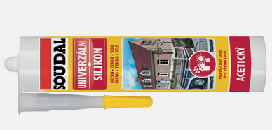 | Universal transparent silicone sealant | 100g |
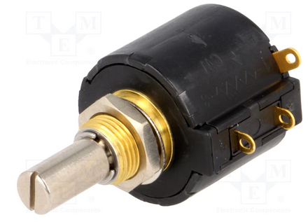 | Azimuth potentiometer Bourns 3547S-1AA-102A | 1 piece |
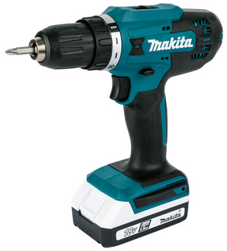
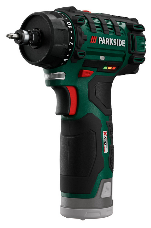 | Motor from PARKSIDE PBSA 12 D4 drill From May 2026 availabe mount for motor rev F5, TNX OK1GOD! | 1 piece |
| 2x 1.5mm wires, 20 cm long | 1 piece | |
| 3x 1.5mm wires, 40 cm long | 1 piece | |
 | crimping ends for guides | 5 pieces |
| Universal lubricant | 200g | |
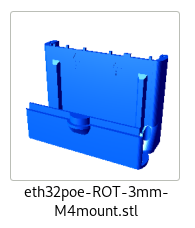 | 3D print box for Simple Rotator Interface V. electronics (optional) Mounted in step 16 | 1 pieces |
Tools
 | Drill 8,2mm |
 | Drill machine |
 | Allen key 2mm |
| | Allen key 2,5mm |
 | Key 5,5mm |
| | Key 7mm |
 | Solder station |
 | Crimping tool |
 | Vise |
 | Set for cutting threads M4 |
 | Protective gloves for applying lubricant |
Assembly manual, step by step
- Before disassembly drill tool for extract motor, set the gear ratio to 1 (slow), and the torque to maximum (drill)

- Remove the two U-shaped springs from the battery space


- Unscrew the seven screws, remove the chuck and open cover

- Sign polarity on the motor (+ on red wire)

- Solder 20 cm of power cable with crimped ends

- The wago terminal block is suitable for general use, for the connection of the Simple Rotator Interface V. use the prescribed connector


- Make sure the gear ratio stick is set to the slow position

- Insert the motor into the half of the printed plastic housing 8.stl

- The orientation of the motor can be seen in the photo. The plastic wheel in the middle is facing up.

- Again make sure the gear ratio stick is set to the slow position

- Apply silicone sealant around the entire perimeter of the plastic holder
Fix the gearbox spring in the slow position with silicone
- Close the motor using the second pulley of the plastic motor holder, and secure with a minimum of four M3x10 screws with a lock nut on each side

- Install three M3x6 screws around the perimeter so that they do not collide with the three protrusions from step 8. Tighten very sensitively, the screws do not have metal nuts, but screw directly into the plastic.

- Press the 6.stl gear onto the motor shaft so that the side holes are directly against the depressions in the motor shaft. Then screw three M3x10 screws into the hole - screw in sensitively and stop as soon as the resistance increases - it is screwed directly into the plastic. We recommend applying secondary glue to the plastic hole before inserting the screw.

- Attach the entire motor body to the rotator 7.stl main tank using four M4x16 screws with lock nuts


- If you will use the Simple Rotator Interface V. to control the rotator, screw its printed box with two M4x16 screws directly to the plastic body of the rotator

- In the next step, drill out the axes of the plastic parts number 1, 2, 3, 4, 5 and 9, with a drill with a diameter of 8.2 mm, so that they rotate freely on a smooth axis with a diameter of 8 mm.


- Fit the four smoothed axes into the rotator body

- You put the metal washer on the central axis, and the low ring from the 9.stl on the opposite axis of the motor

- Now you will fit the gears. Apply universal lubricant to them before putting them on

- Place gear number five on the central axis, and the metal washer on the opposite axis of the motor

- The previous picture has the center gear turned backwards. Turn the bottom gear so that the V slot on the top faces the next gear above it. Then put gear number 4 on the axis opposite to the motor so that its V slot is facing the center axis, and slide the metal washer onto the center axis.

- On the two free axes, you put on the higher printed washers of the 9th stl and on all the outer axes, you put on three metal washers.

- Detail of the orientation of the cogwheels, including the V-groove

- Before fitting other gears, don't forget to lubricate them with universal grease

- Place the 3.stl gear on the center axis so that the V splines point to the surrounding axes

- Place the three 2.stl gears on the edge of the axle so that the number marking points to the center axle

- Detail of mutual position

- Place the metal washer on the center axis

- Insert four M8 screws into gear 1.stl

- Place the 1.stl gear on the center axis

- Now screw the three-step potentiometer to part 12.stl, with orientation according to the picture.

- Using a vice, very carefully press the 11.STL gear onto the potentiometer shaft as shown in the picture

- Solder three 0.5mm^2 wires, 20cm long, to the potentiometer. Crimp the ends with end caps

- Cut M4 threads into the three holes of the main stainless steel plate as shown in the picture

- Set the azimuth potentiometer to the center position, and screw it to the main stainless plate using two M4x16 screws, plus nuts.


- Push the wires through the body of the rotator - pay attention to the orientation - they belong to the tunnel located below

- Place the main stainless steel plate on the rotator body so that the outer axes pass through the plate outwards and secure 21 M4x16 screws. Tighten the screws sensitively, they are cut directly into the plastic

- Apply silicone sealant to the perimeter groove of part 10.stl

- And screw it with three M4x16 screws to the main stainless plate

- apply a small amount of silicone sealant to the center wheel and then slide part 13.stl onto it

- Now the rotator is complete, ready for use

- An example of using a rotator under a mast


3d-print-rotator.txt · Last modified: by ok1hra