Table of Contents
Simple Rotator Interface V. (release 2023)
Web interface with MQTT an USB support
Quick start guide
Hardware
Supported:
- Three type azimuth potentiometer
- three wire from 500Ω to 10kΩ resistance
- grounded two wire from 500Ω to 1kΩ
- thre wire, used one turn from multiturn (typicaly 10kΩ)
Two azimuth pulse (CW/CCW) inputs- NOT implemented yet- DC motor up to 28V/3A with smooth start/finish (PWM)
- AC motor max 50V/8A
- Brake max 50V/8A
- Natively supports 3D printed rotator
- Optional external control unit Gyrotator
Source
- Firmware
- 3D print model case
- Enclosure .stl for POE injector
- Enclosure .stl (version mount on 3D print rotator)
- Electronics
- .PDF schematics
- Optional 3D print rotator
- Optional external control unit
Functionality
- Remote powered by POE - need 13,8V to 15V/500mA source, mounted to 35mm DIN rail


- Switching between three and two wire azimuthpotentiometer in setup page
- Enable preamp and shift op amp in setup page
- Local control with CW paddle via 3,5mm stereo jack connector
- Galvanically isolated AC or DC motor control, including DC PWM
- Working rotator without hardware endstops - replace by two (low/high) software adjustable forbidden zones in end positions
- MQTT for integrated to your main ecosystem, typicaly NodeRed
- MQTT Wall - web clent shown all topics included
- Overlap support, for example 405° range, with rotate to short direction
- Usable nearest to rotator, directly on tower, or in hamshack
- Status LED while using front panel preset knob (indoor desktop use only)
- LED showing fuse failure on main board or POE interface

- Three safe stop watchdog - 60 sec after firmware without answer, max 90 sec rotate, max 10 sec without 10 grad azimut change during rotate
- Under 11V voltage POE power watchdog
- Warm up timer for stable value during setup
- Firmware detects the hardware version and displays it in the web interface
- Optionaly controled (via MQTT) by Gyrotator independent hardware based on M5Stack fire https://github.com/ok1hra/gyrotator


Four mounting methods
Outdoor on tower   | Outdoor, part of the 3D printed rotator (optional)  |
Indoor on 35mm DIN rail  | Indoor to your desktop (optional)  |
Six control source at the same time
| Web interface with azimutal world map, containing the current grayline 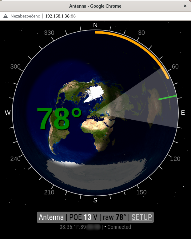 | Gyrotator Optional controller on external hardware 5Stack FIRE  YouTube video | MQTT (mqtt-wall include) 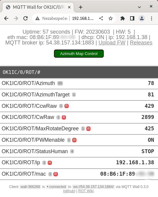 |
| USB GS-232 protocol (commands: R L A S C Mxxx O F) 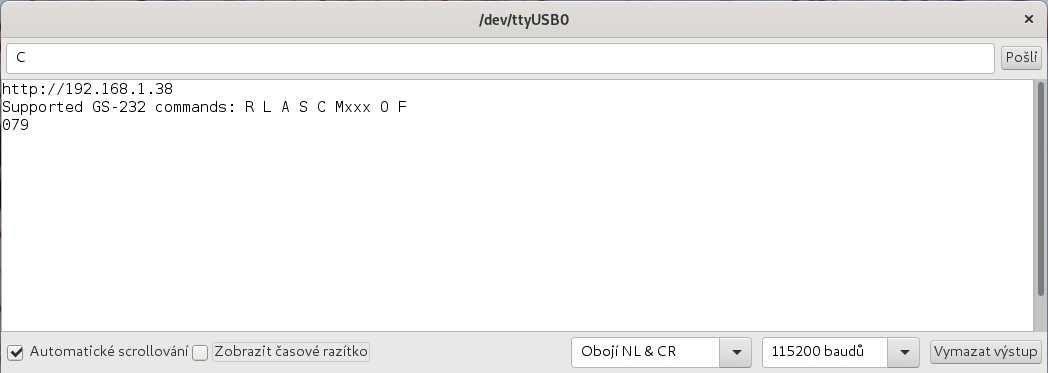 | CW paddle - indoor desktop use - or for manipulate with rotator on DIN rail, or on mount on tower  | Optional front panel preset knob works independently without a GUI, together with the status LED (indoor desktop use only)  |
WiFi e-ink display
- The last azimuth remains on the display even after turning off the rotator.
- Optional display on external hardware from LaskaKit - ESPink-42 ESP32 e-Paper
- It is not used to control the rotator, only to display its rotated state.


Web interface
- Adjustable width of the antenna radiation angle

- Rotate with one click to map
- If click during run, stopped rotation
- Smaller range than 360° shows end limits
- Show connected status between web page and rotator


How to assembly
Need for assembly and run
- Solder station
- Two Allen key 2 and 2.5 mm
- Flat screwdriver, 2.5 mm wide
- Ohmeter (for ten turn azimuth potentiometer only)
- Drill with a diameter of 6 mm (optional for front panel)
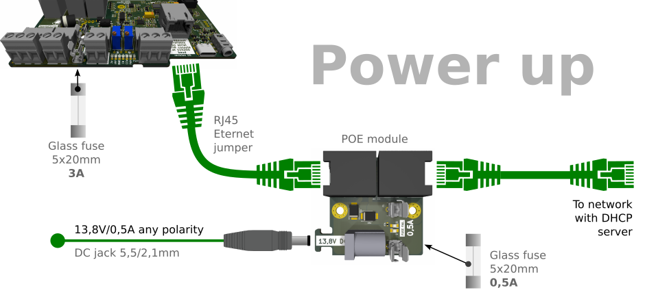
- Two RJ45 ethernet cable for connecting to local network with your prefered length.
- Local ethernet network with running DHCP server.
- 13.8V/0,5A power supply for POE injector
- Power suply for motor yours rotator. AC or DC and voltage according to type.
Assembly steps
- Check that all components are complete

- 3D printed components + two M3 x 10mm screws

- PCB with SMT components

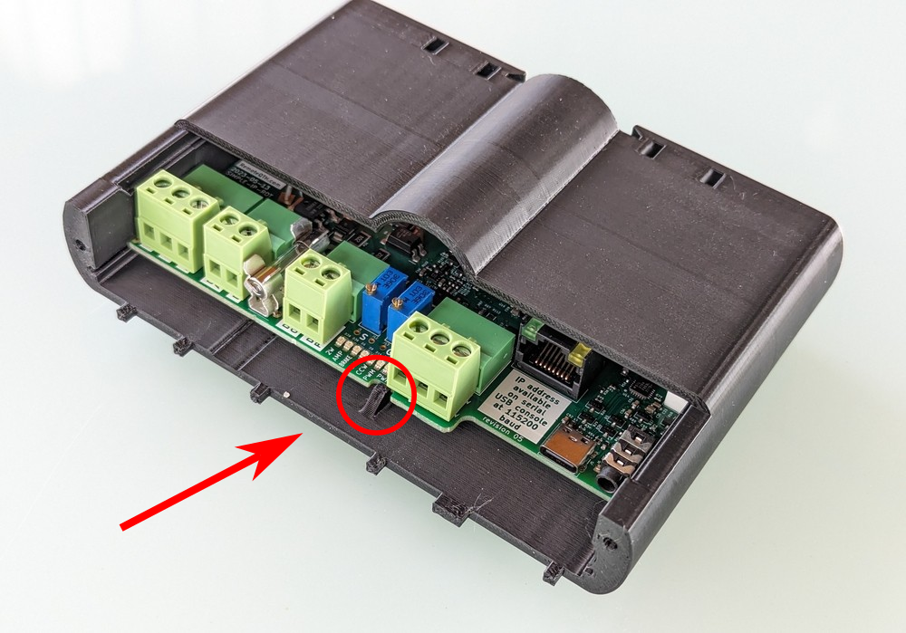
- If the PCB is delivered in a 3D printed box, you can remove it by lifting the PCB at the place where the plastic stop is and pulling it towards you - see picture

- Solder the DC jack first

- For better mounting, fit the fuse terminals with fuses

- Solder the 3A version between the input connectors

- Solder the 0.5A version to the POE module

- Check the fuse values carefully. The opposite assignment will cause a failure

- 0.5A in the POE module
- 3A between input connectors
- In the next step, solder two RJ45 connectors to the POE module

- Solder the diode D24 - attention to the polarity, the white strip is on the side marked K

- Use a screwdriver to unlock the metal casing of the RJ45 connector

- Remove the metal cover and discard it

- Solder the connector to the board

- The PCB board currently looks like this

- Solder the two (blue) potentiometers so that the control screws are facing outwards from the board

- Now solder the three relays


- Carefully break off the POE module

- Use pliers to break off the remaining bridges

- Now you can slide the board into the slots in the 3d printed box so
- that the center latch engages when fully inserted

- The back cover is held with its two latches

- We insert the POE module into the 3D printed box

- And screw the lid on with two screws. Attention, we tighten lightly, the screws are screwed directly into the plastic

- The side to which the power supply DC jack is connected is intended for connecting electronics
- The supply voltage is 13.8-15V DC (500mA) with any polarity
- Breakage of the fuse in the POE module is signaled by the LED below the fuse


Assembly optional front panel
Front panel and potentiometer control is an optional extension. All other control options, including the web interface, remain and work in parallel. Only the other options will not turn the front panel potentiometer, so if used, the front panel potentiometer setting will not match.
- Check the presence of all necessary components

- Solder the connection cable to the potentiometer. Attention, it is necessary to observe the positions of the colors of the wires


- Glue the four rubber feet to the underside of the 3D printed model as shown

- Force push/punch the plug in the center of the front of the 3D printed box

- Drill the indicated hole in the front part of the box, intended for the LED, with a 6mm drill bit

- Insert the potentiometer with the soldered jumper from the inside into the prepared hole and tighten the nut slightly

- Place the front panel and screw in two M3 x 10mm screws - tighten the last threads carefully, the screw is screwed directly into the plastic

- When using the potentiometer on the front panel, jumper J19 must be open. If it is shorted, remove the tin connector by suction with a wire puller

- Put the knob on and gently tighten with a flat screwdriver - calibration of the exact setting is done later from the web interface, setup page. More in the Setup and calibrate section


- Solder LED diode wit orientation beveled side into the slot marked R

- Overhang of the diode over the edge of the PCB at least 12.5 mm

- The distance above the PCB should be 4.0 mm

- Insert the PCB into the guide grooves of the box about halfway and plug in the potentiometer connector. Pay attention to the polarity, the connector can only be inserted in one position.

- Insert the whole PCB into the box until the locking tooth in the middle engages.

- After installing the back cover, the upgrade to the front panel is complete.

- You can continue by connecting the rotator.


Upload firmware
Compile
- Install Arduino IDE rev 1.8.19
- Install support for ESP32
- Install these libraries in the versions listed
- WiFi rev 2.0.0
- EEPROM rev 2.0.0
- WebServer rev 2.0.0
- Ethernet rev 2.0.0
- ESPmDNS rev 2.0.0
- ArduinoOTA rev 2.0.0
- Update rev 2.0.0
- AsyncTCP rev 1.1.1
- ESPAsyncWebServer rev 1.2.3
- FS rev 2.0.0
- AsyncElegantOTA rev 2.2.7
- PubSubClient rev 2.8
- Wire rev 2.0.0
- Select board 'OLIMEX ESP32-PoE'
- Connect the rotator with a USB-C cable and select the corresponding port in the arduino IDE
- Now you can compile and upload code using USB
Compile + OTA update
The firmware can be uploaded via Ethernet under the following conditions
- The Simple rotator board already contains firmware
- The Simple rotator board is connected to the Ethernet with a DHCP server
- The Simple rotator board is powered by a POE module
Now in the Arduino IDE you can select the /Tools/Port/Network port in the menu, the item starting with ROT with the IP address corresponding to your rotator.
At this point it is possible to compile and upload the firmware using the Arduino IDE.
The Arduino IDE will ask for a password during the upload, which is 'remoteqth'.
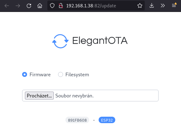
Upload binary via web interface
If the previous three conditions are met, you can upload the firmware binary using the web interface.
- Open url http://[YOUR IP]:82/update
- Also available from the header of the first page as a link | Upload FW |
- Download last release .bin file from GitHub https://github.com/ok1hra/IP-rotator/releases
- Upload .bin file via web form, with the Firmware option selected

- ATTENTION, after uploading, it is necessary to restart the rotator by disconnecting and reconnecting the power supply.

Connection
General description of connectors, individual variants detailed below
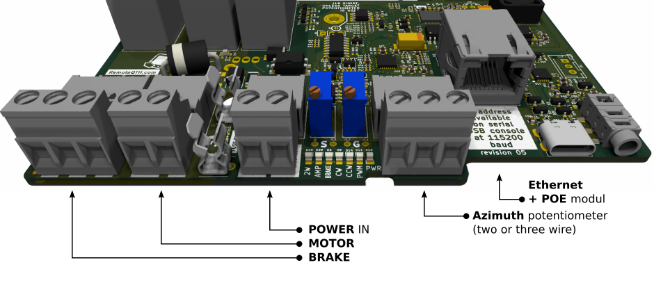
POE power module
LED showing if fuse failure on main board or POE interface

Azimuth potentiometer
Note the connection polarity for systems that share a GND potential
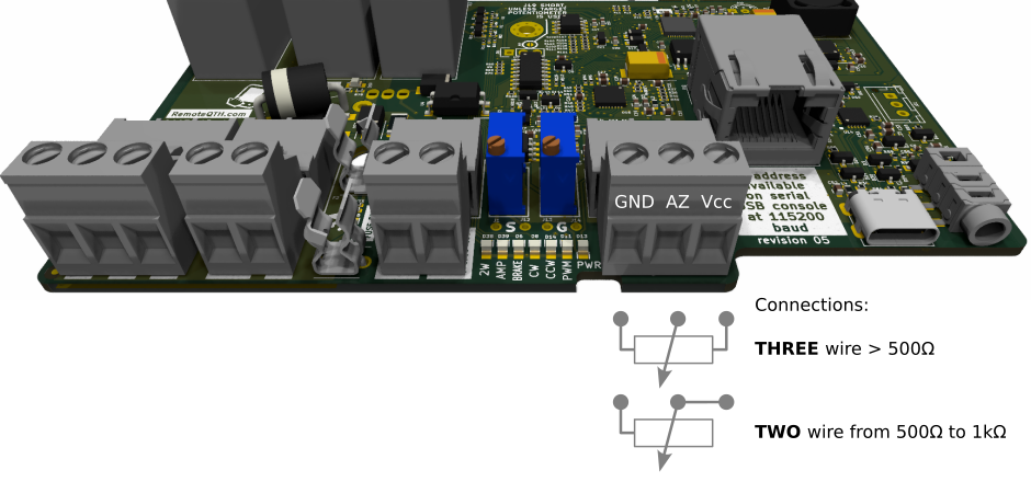
- The type potentiometer used must also be set in the web interface, Setup page. Option “Azimuth potentiometer” 2wire/3-wire
- When using one turn of a ten-turn potentiometer, also activate the “Azimuth gain/shift op-amp” option to ON. About calibrate more in Calibrate section.
- If you are using a two-wire 500Ω potentiometer, short-circuit jumper J16 on the bottom side of the PCB. Do not use this jumper in other cases.


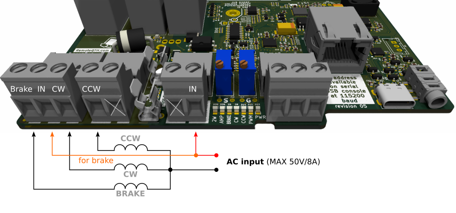
AC motor
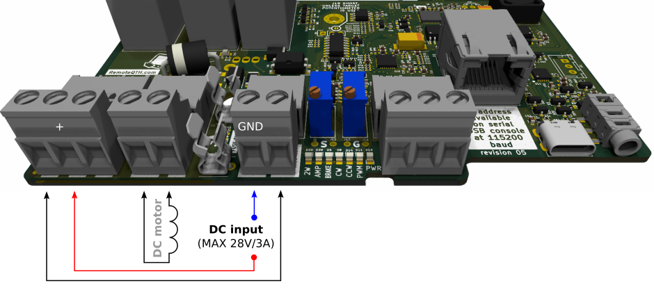
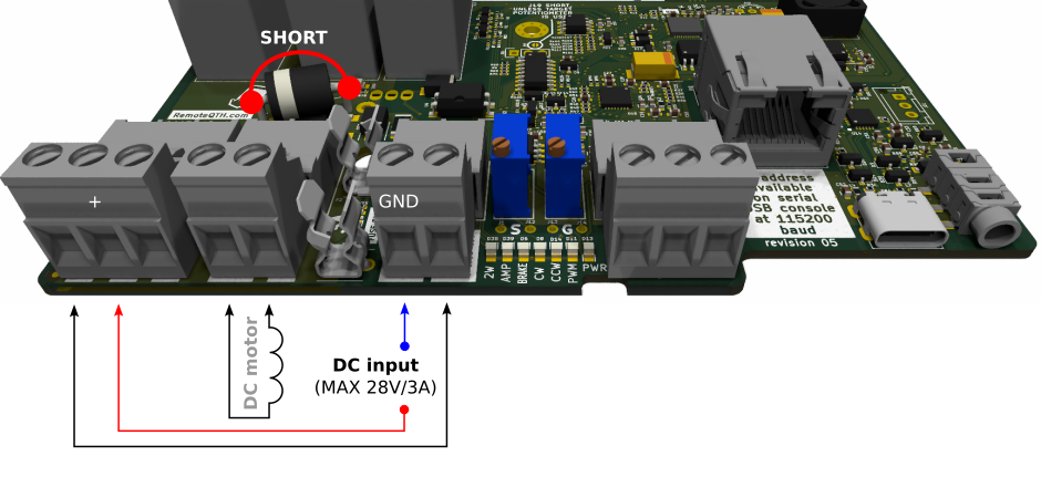
DC motor with PWM
- Activate the PWM functionality on the Setup web page
- ATTENTION
- Observe the polarity of the power supply, otherwise the power mosfet may be destroyed.
- Observe the maximum prescribed loading.
- We recommend using the following safe option with software endstops.
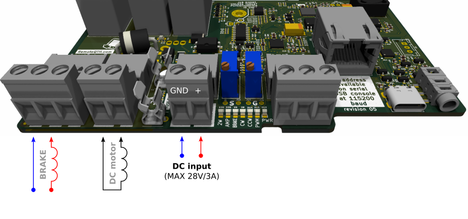
DC motor with PWM, without hardware endstop (safe mode)
- If you use a rotator without hardware endstops, the destruction of one component (power mosfet) can cause the rotator to crash. Therefore, it is safe to connect one more active element in series (relay intended for the brake).
- Activate the PWM functionality on the Setup web page
- ATTENTION
- observe the polarity of the power supply, otherwise the power mosfet may be destroyed.
- observe the maximum prescribed loading.
DC motor without PWM
- PWM can be replaced with an external brake relay
- Deactivate the PWM functionality on the Setup web page
- ATTENTION
- Don't forget to bridge or replace the diode D24 with a jumper.
- Make the jumper with a copper wire with a cross-section of 1.5 mm2


Control, setup and calibrate
LED status
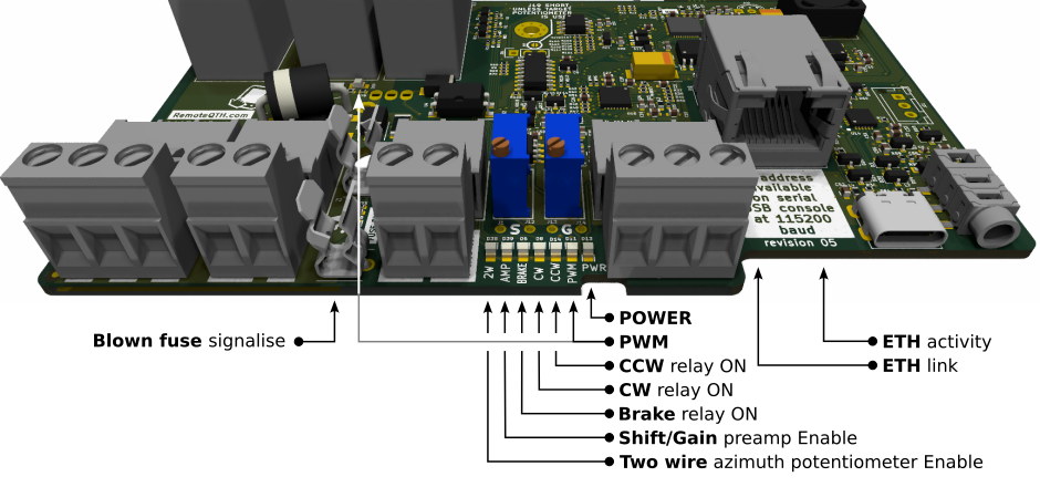
LEDs signal static (PWR) or dynamic (PWM) states during rotator operation
Connect and tune
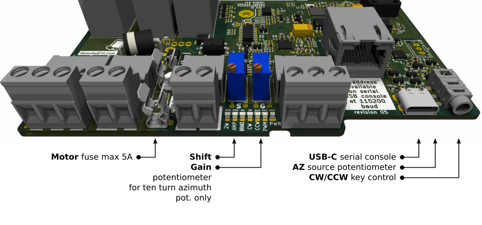
- The fuse for the motor should be optimally 5A
- Two blue, multi-turn potentiometers are used to set the Shift and Gain of the preamplifier in the azimuth measurement mode with the use of one turn from the ten-turn potentiometer.
- The USB-c connector is used for uploading firmware or connecting a serial console. DO NOT use USB-C to power electronics.
- Internal three-pin connector (balls), serves for connecting an optional front panel potentiometer.
- The 3.5mm stereo jack serves for connecting a manual control of the rotator, typically a CW bug.

How to find the IP address of the device
-
- connect POE power supply
- ethernet to a site with an active DHCP server
- Variant via USB terminal
- connect USB-C between rotator and PC
- open Arduino terminal with 115200 baud speed
- press ? and enter
- terminal show your IP address

- The variant can be found using the arduino IDE
- Open Arduino IDE menu Tools/Port/Network port
- The menu will display network devices that contain OTA firmware - the IP address is at the end of the line starting with ROT-

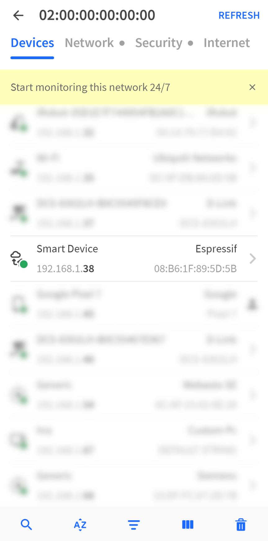
- With the help of the Fing android application
- Install Fing
- Scan local network
- Find device with brand name Espresiff and begin MAC start 08:B6:1F

Settings using the web interface
Main web page
Open the IP address found using the previous instruction in a web browser http://[YOUR-IP]
How to works
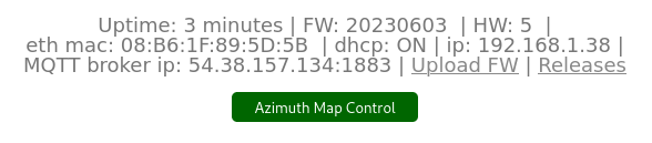
- The first page contains an information header, including a link to the Firmware Upload page and the Release page on GitHub. Give green the button of the link to the control page of the rotator. Below it is the web MQTT client (credit MQTT wall) displaying the data sent or received by the rotator from the MQTT broker - data used to control or debug the rotator.
Control web page
How to works
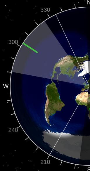
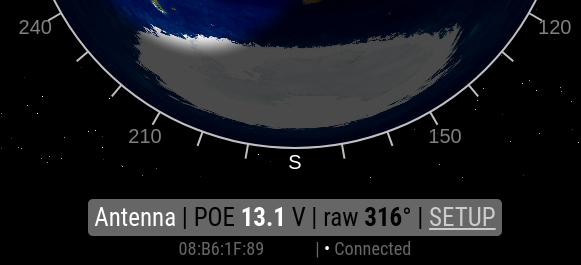
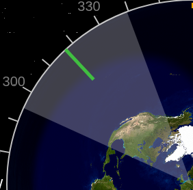
- The basis for the display is an azimuthal map, centered in your QTH. The map shows the current grayline. Map settings are made in the Setup page, item Background azimuth map URL.
- The direction of rotation indicator is a transparent triangle whose angle corresponds to the width of the antenna's radiation pattern. The center is marked with a green pointer on the scale. The width of the radiation diagram is set in the Setup page, item Antenna radiation angle in degrees.
- COLORS - If the direction is in the free range, the indicator color is green. If the pointer reaches the overlap zone, the color is yellow. If the rotator is in rotated mode, the indicator color is red. If the rotator reaches the endpoints, the color is gray.
- The yellow line on the edge shows the Overlap zone. It is the angle by which one 360-degree revolution is extended.
- Gray bar on the bottom shows. | Antenna name - set in the Setup page, Rotator name item. | The power supply voltage controls the electronics from the POE injector - if it drops below 11.5V, the watchdog stops the rotator. | Raw angle rotated - angle without displacement, as if it were zero degrees north. | Link to the Setup page.
- Below the gray bar is shown, MAC address of the Ethernet interface and website connection status with engine electronics. If it is not connected, the data on the website is not up to date and the rotator cannot be controlled.
- CONTROL - by tapping on the map, the azimuth is calculated and the rotation starts. Emergency stop is performed by clicking anywhere on the azimuthal map again.
- Tip: for a short movement of the rotator, you can click on the map twice in close succession. The motor will only turn on for this time, including the PWM start/stop sequence.
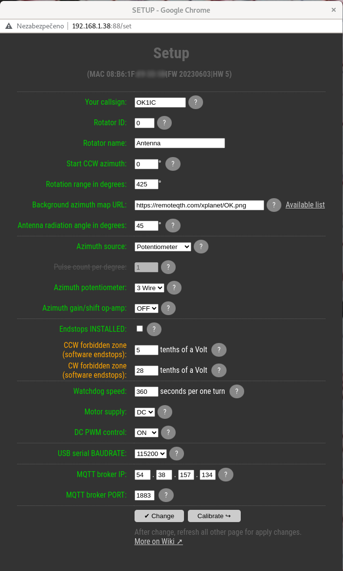
Setup web page

How to works
- The Setup page is used to set the basic properties of the rotator.
- You will notice that the hints for individual items are hidden under the question mark at the end of the line.
- Your callsign and Rotator ID are unique identifiers used to generate an MQTT topic in the form [callsign]/[ID]/ROT/[variable]. Changing these values requires a reload of the first page with the web MQTT client. After the first power-on, for the Callsign firmware uses the last five characters from the MAC address until a new setting is made.
- Rotator name is used to identify the rotator on the web control page.
- Start CCW azimuth is the end value of the start of rotation in the counter clockwise direction. This is the azimuth that the rotator is rotated in real conditions, if it is in this end position.
- Rotation range in degrees is the rotation range of the rotator between two (CCW and CW) endpoints in degrees.
- Background azimuth map URL is a link to a web file with a bitmap azimuth map. Generation of own map is described in chapter Run own services
- Antenna radiation angle in degrees, is the value of the width of the radiation angle of your antenna, which will be applied in the display of the control page.
- Azimuth source is a choice between a signal source for azimuth determination. The potentiometer is the default value. The CW/CCW pulse function is then not implemented now.
- The azimuth potentiometer is a choice between two and three-wire variants. The two-wire variant uses a constant current source of 9mA and enables the connection of a potentiometer smaller than 1kΩ. The three-wire variant uses a constant voltage source of 9V and enables the connection of a potentiometer of 500Ω or more. You can find the connection in the Azimuth potentiometer section.
- Azimuth gain/shift op-amp, is turned ON, ONLY when using a multi-turn three-wire potentiometer, of which only one turn is used. Because one turn generates a small change at the input of the AD converter, it is possible to help amplify the preamplifier. How to do it:
- The first step is to set the trimmers R80 and R81 to the default position. Connect the ohmmeter to the measuring point S (J1, J12) and turn the trimmer R81 counterclockwise until the ohmmeter shows a value close to 0Ω. We repeat the same thing with trimmer R80 and measuring points and G (J13, J14).


- This setting assumes that REVERSE-CONTROL and REVERSE-AZIMUTH are correctly set in the Calibration page.
- The second step is to physically turn the rotator up to the CCW endstop, which will not cause the AD converter input to shift to the left edge of the scale on the Calibration page. Therefore, we start moving the value towards the left endstop on the scale by turning the potentiometer S (R81) clockwise until we reach the left endstop on the scale, ATTENTION, after reaching the edge of the scale, do not continue turning the potentiometer, the input value of the AD converter must still move within the range scale.
- The third step is to physically turn the rotator up to the CW endstop, which will not cause the AD converter input to shift to the right edge of the scale on the Calibration page. Therefore, we increase the gain of the preamplifier by turning the potentiometer G (R80) clockwise until we reach the right endstop on the scale. ATTENTION, after reaching the edge of the scale, do not continue turning the potentiometer, the input value of the AD converter must still move within the range of the scale.
- We repeat the previous two steps until we achieve the desired result.
- Then calibrate the SAVE-CCW and SAVE-CW endpoints on the Calibration Page.
- Endstops INSTALLED, turning off this item activates software endstops, which are prohibited zones on the edges. The size of these zones is set in the following two items. If this item is enabled, the firmware relies on the hardware endstops in the rotator, including that they are not beyond the range of the measure potentiometer.
- CW/CCW forbidden zone (software endstops), are values of the range of forbidden zones in millivolts. the entire range of the rotator represents a voltage of 0 to 3.3V. The setting value will appear in the Calibration page as a yellow area at the edges of the range. If the rotator is set correctly, it only allows movement in the direction from the edge to the center. Keep the protection zone large enough to prevent damage to the rotator.
- Watchdog speed is the minimum rotation speed in seconds per one turn, which if the rotator does not reach, it will be stopped by the watchdog. Use a value at least 50% higher than the real speed to avoid false stops.
- Motor supply, is a choice between AC and DC rotator type. The DC type enables the activation of the PWM start-up and run-down ramps.
- DC PWM control activates the PWM ramp-up and ramp-down when using the DC rotator. If you use a rotator without hardware endstops, the destruction of one component (power mosfet) can cause the rotator to crash. Therefore, it is safe to connect one more active element in series (relay intended for the brake). This setup is highly recomended, see Connection section. Turning DC PWM on activates two other settings:
- PWM ramp length in steps of 25ms + displaying the length of the ramp in seconds, allows you to set how long the PWM control will regulate from 0 to 100% during acceleration, or vice versa during deceleration - WARNING - a longer ramp may result in passing the end points, it is therefore necessary to set sufficiently large margins in CW /CCW forbidden zone (software endstops). In this way, imprecise stopping will occur more often due to the overlapping of the starting and stoping ramps when rotating through small angles.
- PWM ramp start distance the distance from the target azimuth in degrees, from which the PWM ramp starts, the length of which is set by the previous value.
- By combining both values, it is possible to tune the PWM sequence so that the rotator stops as close as possible to the required azimuth. YouTube video show two parameter settings
- If there is a need to rotate to a closer azimuth than twice the “PWM ramp start distance” value, there will be a switch from the starting to the stopping ramp halfway through the journey, which affects the stopping accuracy (missing the entire stopping sequence in the combination of time and distance). Therefore, it is better to choose both values as low as possible for your antenna assembly, so that it does not overlap the start and stop ramps.
- USB serial BAUDRATE, is the setting of the communication speed of the serial console on the USB-C connector using the GS-232 protocol. Enabled commands
- ? display the IP address of the rotator
- R clockwise rotation
- L counter clockwise rotation
- A or S CW/CCW rotation Stop
- C show antenna direction value
- Mxxx rotate to azimuth, degree represent with three number
- O CCW calibration
- F CW calibration
- MQTT broker IP, IPV4 address of the MQTT broker server
- If the first digit is zero, MQTT is disabled
- MQTT broker PORT, number of the IP port on which the MQTT broker runs.
- Change button, save actual value.
- Calibrate button open Calibration web page.


Calibrate web page
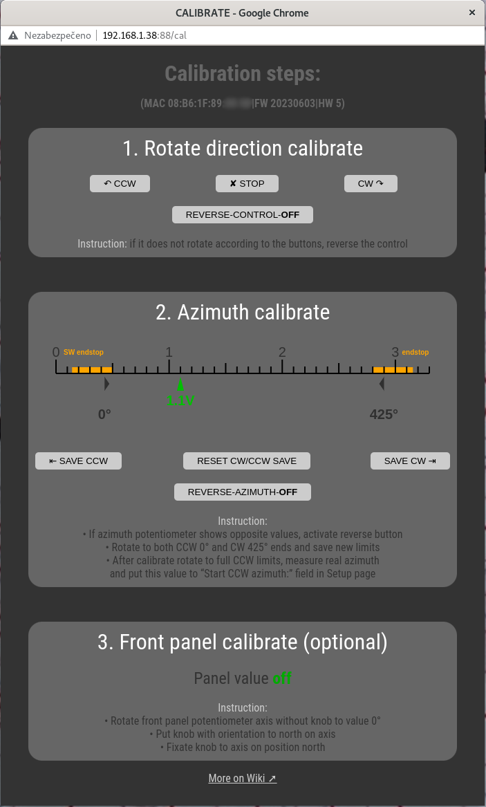
Calibration is divided into three steps
- Rotate direction calibrate
So that it is not necessary to observe the polarity of the rotator motor connection, you can use the CCW, CW and STOP buttons to test the direction of rotation. If the rotator rotates in a different direction than the control button, you can reverse the direction using the REVERSE-CONTROL button. - Azimuth calibrate
The scale shows the status of the input AD converter in the range of 0 to 3.3V. Due to activated software linearization, regions in the range of tens of mV are not available. If software endstops are activated in the Setup web page, the prohibited zones at the edges of the range will be displayed in yellow. In the lower part there is an arrow showing the current read value of the AD converter. There are gray arrows on the edges, showing the calibration values of CCW and CW stops. How to calibrate:- Turn the rotator briefly using the CW, CCW and STOP buttons in the previous section and watch the movement of the current value of the AD converter. The correct direction is left for CCW and right for CW. If the arrow moves in reverse, invert it using the REVERSE-AZIMUTH button
- Then rotate the rotator counterclockwise until it is stopped by a software or hardware endstop. After stopping, save the value with the help of the SAVE CCW button.
- Continue rotating the rotator clockwise until it is stopped by a software or hardware endstop. After stopping, save the value with the help of the SAVE CW button.
- The RESET CW/CCW SAVE button is used to set the default values if the setting needs to be repeated.
- After calibrate, rotate to full CCW limits, measure real azimuth, and put this value to “Start CCW azimuth:” field in Setup page.
- Changes to settings in the map control page will be reflected after the page is reloaded.
- Front panel calibrate (optional) if install Optional front panel you can calibrate knob
- Rotate front panel potentiometer axis without knob to value 0°
- Put knob with orientation to north on axis
- Fixate knob to axis on position north
Control via optional front panel
The front panel contains only two active elements:
- Button for setting the required azimuth - if the front panel is installed, turning the knob will make a quick change of the target azimuth, but it is not very accurate. The rotation of the rotator can be monitored on the control page of the web interface, or via MQTT, optionally also on the Gyrotator unit. Attention, the direction of the control knob on the front panel will no longer correspond to the real rotation of the rotator, if you change its azimuth from another source, for example from a web browser.
- The status LED has three states
- RED lights up during rotating.
- GREEN lights up if the rotator has reached the set azimuth and stopped.
- FLASHES GREEN if the rotator has stopped and has not reached the target azimuth.
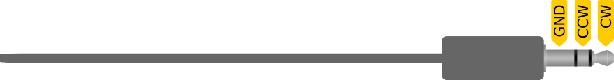
Manually controll
Manual control is available via the 3.5mm stereo jack connector on the back of the electronics. By switching the left or right channel, it is possible to control clockwise or counterclockwise rotation. Connection is here.
Your CW key can easily be used as a switch control.
This control is suitable for service movements or if you operate the Interface on your desk.
Running own services
MQTT broker
MQTT is a universal protocol that is used to communicate the rotator with other devices. The control node transmitting this information is the MQTT broker. The default settings of the rotor use the public MQTT broker of the Internet at the address remoteqth.com. In order to avoid dependence on an Internet connection or the availability of a public MQTT broker, we recommend that you install your own MQTT broker on a Raspberry PI or other device in the local network. For this you can use some of the public instructions like this one (without installing NodeRed).
After installation, change the settings of two items (MQTT broker IP and MQTT broker port) in the Setup section, according to the IP address of your local MQTT broker.
Background azimuth Map generator with grayline
The RemoteQTH server provides a live grayline world map generation for selected DXCC countries at address https://remoteqth.com/xplanet/ (adding others upon request from OK1HRA). The entire path to the map is entered in the Setup page in the item Background azimuth map URL.
If you don't want to depend on the internet connection or remoteqth.com server functionality, you can run the real generator on any Linux machine, for example Raspberry PI. You need two functions for this:
- http server, example here
- Script generating bitmap
- Install xplanet with code
sudo apt install xplanet xplanet-images
- Create line in /etc/crontab
*/15 * * * * web /usr/bin/xplanet -window -longitude 13.8 -latitude 50.0 -geometry 600x600 -projection azimuthal -num_times 1 -output /var/www/remoteqth/xplanet/OK.png
Where to replace | web user a valid user of your system | numerical coordinates of longitude and latitude with your requested coordinates | path /var/www/remoteqth/xplanet/ for the path published by your web server | file name OK.png for your desired file name
- Enter the resulting path to the generated bitmap in the Background azimuth map URL item on the Setup page.
Online Map generator
Available on URL ok2pbq.atesystem.cz/prog/ae_map.php
Known bugs
- If the continuous draw of your motor does not exceed the allowed limit, but the fuse still blows, the problem may be in the starting current. This current is naturally limited by the length of the power cable. If the problem persists even with the rotator on the mast, supplement the connection with a starting resistor (B57237S0109M) in series with the rotator motor.