Table of Contents
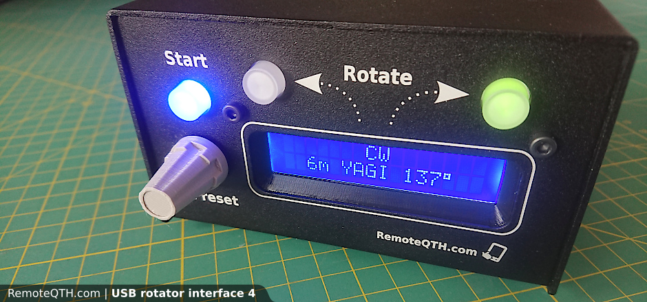
USB rotator interface 4
Web page
Order
Version 3 ← USE FOR PREVIOUS REVISION
New features
- independent power GND
- support two wire or grounded center azimuth potentiometer
- support ten turn potentiometer
- support cw/ccw pulse inputs
- compact small smd layout
- better mechanical assembly with 3d print parts
- robust usb-B connector
- support PWM start/stop with DC power (optional)
Hardware
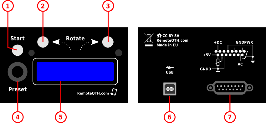
- Start light button
- CCW rotate light button
- CW rotate light button
- Preset encoder
- LCD display
- USB-B connector
- D-Sub 15 pin connector
D-Sub 15 pin connector layout
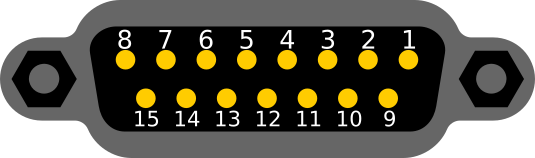
| Pin number | AC motor functionality | DC motor functionality |
|---|---|---|
| 1 | - | DC motor (+) output |
| 2 | ||
| 3 | AC motor output CCW | DC motor (-) output |
| 4 | ||
| 5 | GND (power input) / (motor output) | |
| 6 | GND digital (USB) input | |
| 7 | AC motor output CW | DC (+) power for motor input |
| 8 | ||
| 9 | AC power input | - |
| 10 | ||
| 11 | AC brake output | DC brake output |
| 12 | PULSE CW input - open collector with 10k pull up to +5V | |
| 13 | PULSE CW input - open collector with 10k pull up to +5V | |
| 14 | Azimuth input 0-5V DC from potentiometer | |
| 15 | +5V DC input (max 400mA) also for azimuth potentiometer | |
| shield | GND (power input) / (AC motor output) | |
Voltage/current carrying capacity is limited by the relays used, see datasheet.
Sources
.PDF | Schematics 4.0.3
.html | Interactive BOM 4.0.3
.STEP | 3d model 4.0.3
.zip | KiCad source 4.0.3
3D models
LCD.scad - source
LCD.stl
LCD.3mf
- for PrusaSlicer
knob.scad - source
knob.stl
How to assembly

What tools do you need to build
- Tin
- Solder
- Pliers
- Splitters
- Phillips screwdriver
- Small flat screwdriver
- + 2,5mm imbus (packed in KIT)
- Ohmetter (for op-amp preset)
- Electric drill and 3.5mm drill bit for DC PWM (optional)
Steps of assembly
For finding any components use .html | Interactive BOM 4.0.3 with search window.
The estimated difficulty of the assembly - for moderately advanced solder maker.
- Check all parts

- First time solder three connectors P2,P3, P4

- Connect USB cable to Rotator interface and your PC, and check (device manager in windows) that the USB converter has been recognized correctly. Contact us if you have any problems and do not continue assembly.

- Solder pinheader P5, JP2, U1 and pinsocket 6×2 P3
WARNING, do not solder P1!
Explanation: P1 use in factory for upload bootloader to CPU, therefore no further need.
- Solder S4 reset switch

- Cut one of pin S4 switch nearest to S2 switch, see picture

- Solder ten turn trimmer RV1, RV2, RV3 with orientation by silkscreen or picture

- Solder light switch S1, S2 and S3 marked blue - from 2021 year without mark - all is same
Warning - solder this part carefully with regard to nearby SMD components so that they are not damaged
- Put 3D print LCD frame

- Remove protective foil from LCD

- Put on LCD to pinheader and screw the M3x10 into the corner of the plastic frame (without the use of a nut, the hole is conical)

NOTE: if your kit contains an LCD with 2.5 mm holes, use a 3 to 3.2 mm drill bit to enlarge them (4x)
- During solder LCD press the frame and the LCD so that there is no space between them

- Solder all 16 pins

- Break and remove the peg from rotary encoder

- Straighten the two side pins using pliers

- Solder U3 rotary encoder
WARNING - solder this part carefully with regard to nearby SMD components so that they are not damaged
- Open aluminium box and insert two black M3x20 to front panel

- Fit the front panel (by screwing) and lightly tighten the nuts

- If use DC motor continue on white base PCB soldered D2 diode marked 1N4007. For AC is D2 not use!

- Solder D17, D18 zener diode marked BZW04

- Solder R40 resistor (without picture)
- Solder pinheader JP3, JP1, P6 and P2 (cut to 6×2)

- Solder C28 and C29 capacitor marked 472

- Solder V1, V2, V3, V4 varistors marked 180K07D


(From September 2021 change of type from blue to red)
- Solder P4 USB-B connector

- Solder polyfuse F1

- Solder J1 DB-15 female connector

- Solder L2 inductor

- Solder RL1, RL2, RL3 relay

- Connect P2 put in P3 connector and screw two M3x4 to bottom aluminium box spacers

- Screw two black countersunk screws into the bottom rear panel and stick four rubber feet

- Put the knob on rotary encoder axis

- Screw two black countersunk screws into the top cover of alluminium box.
- Next step preset jumpers below and upload test firmware.


Start-up
Jumpers and potentiometers preset
After setting jumpers dependancy to your hardware continue upload test firmware.

- RV1 - set LCD contrast after upload firmware
- JP2
- AC motor OPEN
- DC motor SHORT
- JP3 - enable pull up
- Three wire azimuth potentiometer OPEN
- Two wire grounded azimuth potentiometer SHORT (+ adjust with P5)
- JP1 - enable PWM for DC motor (optional)
- default SHORT
- enable OPEN - must be install Q4
- P6 - select output for brake, between
- AC
- DC
- GND
- P5 - enable op-amp GAIN and SHIFT functionality
- default disable (bypass)
- enable
- RV2 - tune SHIFT
- RV3 - tune GAIN
Install test firmware
This firmware testing harware after assembly and helped you with azimuth potentiometer.
- Install Arduino IDE
- Install Arduino libraries
- LiquidCrystal
- LcdBarGraph
- Download firmware from GitGub
- Select menu Tools/Board:“Arduino Nano”
- Select menu Tools/Processor:“ATmega328P”
- Connect USB cable between Rotator and PC
- Select menu Tools/Port/YOUR-CONNECTED-PORT
- Upload firmware
- After firmware upload PRESET LCD CONTRAST with resistance trimmer RV1
Test functionality - we recommend testing everything
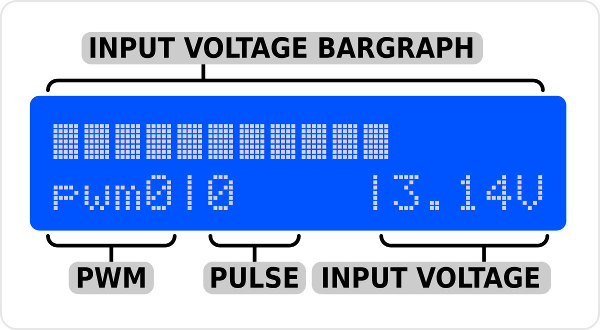
- Measure azimuth voltage input (bargraph and value) - connect azimuth potentiometer and test if analog voltage input work and how is his range.
- Counter CW and CCW pulse input (must grounded to digital GND) - this tested two digital input path.
- Encoder functionality set pwm outputs on LCD and mosfet gate - turn encoder increase/decrease PWM value. If connect PWM mosfet, also test output PWM power from 0 to 100%. With osciloscope also easurable on gate of mosfet.
- Light button feedback and switch relay - every button must light after press and switch on one ofrom three relays (tested input from button and output to light and enable relay).
This firmware use also for tune SHIFT and GAIN op-amp functionality.
Digital power supply
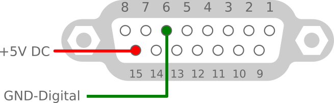
For independent powered without USB. Also better (recommended) way, because USB power produced lower voltage over isolating diode D4.
- Voltage +5V
- Power consumption < 400mA
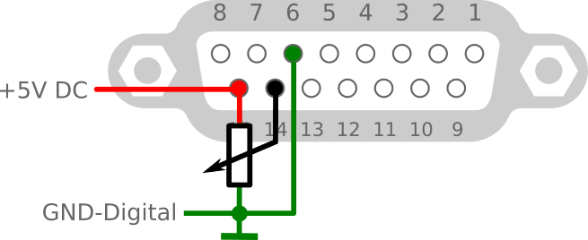
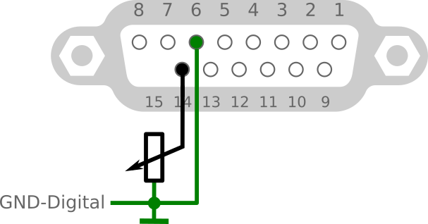
Connect Azimuth potentiometer
3 wire one turn
- JP3 jumper switch OPEN.
- P5 jumper switch to bypass.
- Optimal value is about 600 ohm. Corresponds to 8mA current.
- Avoid values lower than 100 ohms.
- If test firmware indicate range 0-5V, continue by connecting the motor.
2 wire, grounded
- JP3 jumper switch SHORT.
- P5 jumper switch to enable.
- Optimal value is near internal pull-up R40, which is the value 510 ohm.
- Next step Setting gain/shift op-amp - for 2 wire azimuth potentiometer set shift to 0 and increase only GAIN (RV3).
- If preset op-amp indicate in test firmware range 0,5-4,5V, continue by connecting the motor.
3 wire, one from ten turn
- JP3 jumper switch OPEN.
- P5 jumper switch to enable.
- Worked with one turn (or any part) from 10k ten turn potentiometer.
- Next step Setting gain/shift op-amp
- If preset op-amp indicate in test firmware range 0,5-4,5V, continue by connecting the motor.
Connect Azimuth cw/ccw pulse
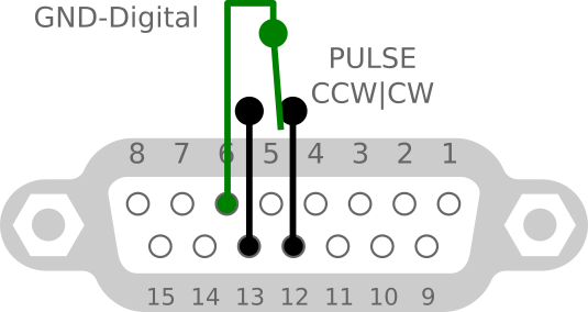
- JP3 jumper switch OPEN.
- P5 jumper switch to enable.
- Input must grounded to digital GND.
- Next step test with test firmware.
- Note: K3NG firmware use only pin12.
Setting gain/shift op-amp
P5 DISABLE shift/gain op-amp (bypass)

P5 ENABLE shift/gain op-amp
Warning - this circuit is sensitive to the stability of the 5V power supply. If enabled, ensure a sufficiently sized 5V power supply with short leads.

With enable, activate circuit two OP-amp for
- SHIFT RV2 level down from up to 3,5V
- GAIN RV3 in range 1-21
For use continue with this step
- First disconnect USB interface from power and turn RV2 and RV3 to start (full counterclockwise if control screw is down)
- Test if RV2 and RV3 on start with ohmeter on test points
- between W1 and W2 for RV2 turn to 0 Ω

- between W3 and W4 for RV3 turn to 0 Ω

- Connect to power and upload test firmware (if not)
- Turn the azimuth potentiometer to the stop, which produces lower voltage.
- Use RV2 for shift voltage down, not 0V - optimally 0,5V.

- for 2 wire azimuth potentiometer shift not set, will remain on 0. - Turn the azimuth potentiometer to the oposite stop, which produces higher voltage.
- Use RV3 for increase voltage up to 4,5V (not full 5V).

- Jump to step 4. and reply for precise tune output between 0,5-4,5V on full azimuth potentiometer range.
- Now ready for upload K3NG rotator fimware.


Connect AC motor

For connecting AC motor power, use only power GND on pin 5 and shield.
Do not use independent digital GND.
For AC motor do not use D2 diode, if install, remove it.
Notice: do not forget to connect the capacitor as well, according to the original connection of your motor.
Connect DC motor

For connecting AC motor power, use only power GND on pin 5 and shield.
Do not use independent digital GND.
Enable PWM
(Optional hardware).
WARNING - use only with DC motor, do not solder if use AC motor.
- Use mosfet type PSMN5R6-100PS,127 from Mouser or other distributor.
Solder Q4 mosfet with distance - see picture
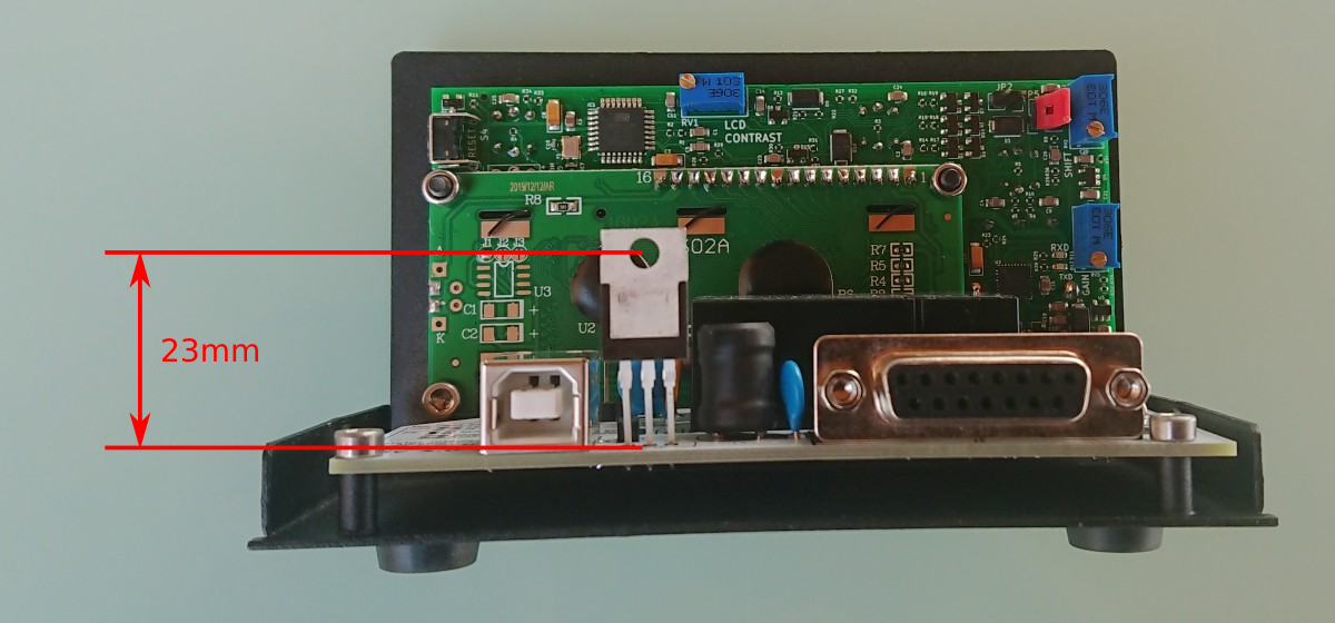
Drill a 3.5mm hole in the rear panel according to the size in the picture

Insert duty rollers and silicone insulation from the outside into the mosfet

Put rear panel and mount to back with two screws.

Insert the inner part of the plastic pin from the side of the mosfet. More power may be needed.

- Remove JP1 jumper (OPEN).
- PWM start stop in preconfigured firmware is enabled and may be more configure.
Firmware
This firmware originaly produced Anthony K3NG, TNX! and source available on GiHub.
For more information use the author's extensive wiki.
- First prepare hardware with Test firmware, after finish continue.
- Install Arduino IDE
- Download firmware - preconfigured version K3NG firmware 2020_08_26
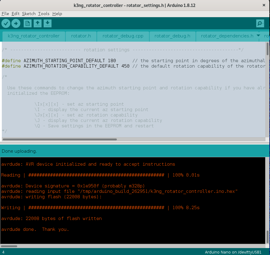
- Open file rottator_settings.h and edit two line which is used to set the azimuth range of the rotator
#define AZIMUTH_STARTING_POINT_DEFAULT 180
#define AZIMUTH_ROTATION_CAPABILITY_DEFAULT 450
- Select menu Tools/Board:“Arduino Nano”
- Select menu Tools/Processor:“ATmega328P”
- Connect USB cable between Rotator and PC
- Select menu Tools/Port/YOUR-CONNECTED-PORT
- Upload firmware

Calibrate K3NG firmware with CLI
This is quick view, for more information use the author's extensive wiki Heading Calibration Command Reference.
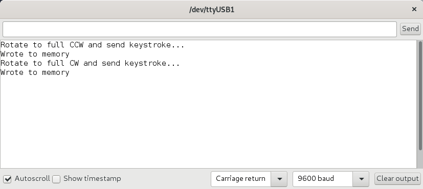
- Open serial monitor in Arduino CLI (Ctrl+Shift+M)
- Set Carriage return and 9600 baud
- Previous start point and range also available preset via CLI
\Ix[x][x] - set az starting point
\I - display the current az starting point
\Jx[x][x] - set az rotation capability
\J - display the current az rotation capability
\Q - Save settings in the EEPROM and restart
- For callibration voltage to preset azimuth range in firmware use
O  - Azimuth offset calibration
F  - Azimuth full scale calibration
- for erase EEPROM command
\E - initialize EEPROM
Setup pulse input
Control software
- PstRotator for Windows
- RemoteQTH server image for Raspberry PI - web interface
- Even software supporting Yaesu GS-232 protocol…
Some tips
- Compiled binary files from release page can windows users upload with utility XLoader
- Azimuth shorts you can replace with prefixes which are in the same direction from your QTH. For example see prefixes from OK.
- And Azimuth you can replace with name your antenna or tower, e.g. 20m YAGI.
- If do not show degree character (°), change in file rotator_settings.h settings to
#define DISPLAY_DEGREES_STRING "\xB2"
If the LCD displays instead of the character degree (°) lower case “alpha” (α), find in source code all string 'char(223)' and replace to 'char(178)'.
TODO
- component BOM