Table of Contents
3D print APRS WX station (release 2023)
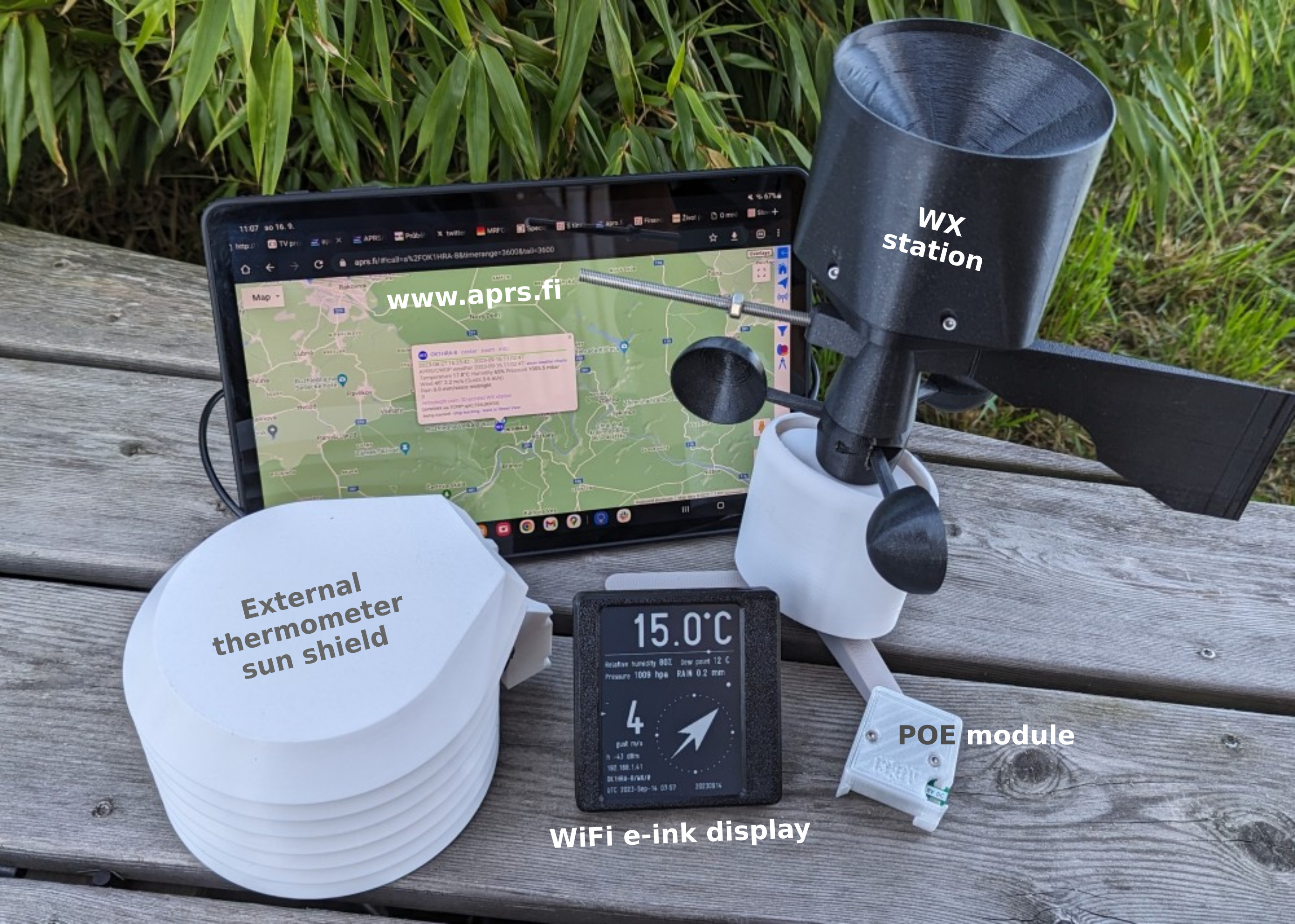
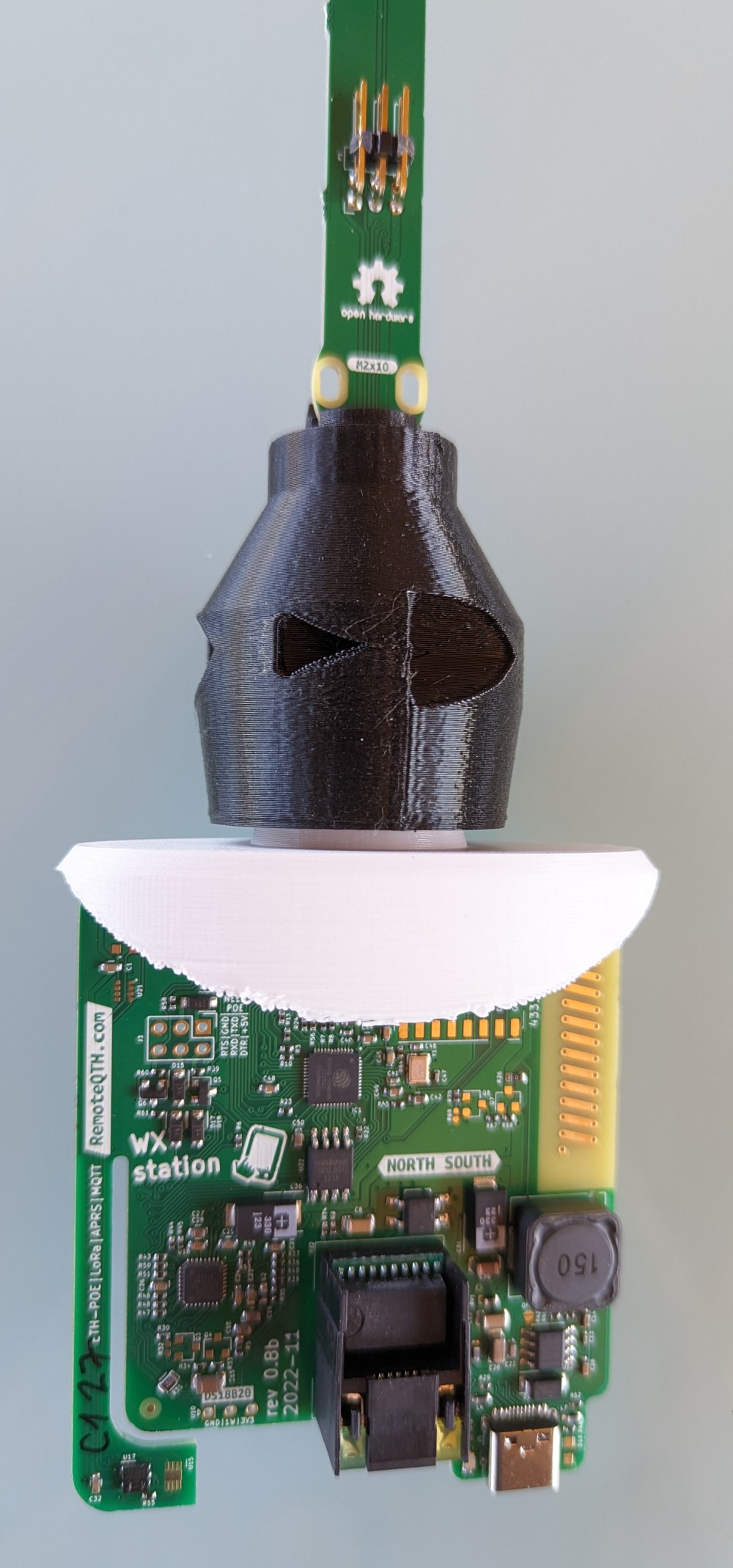
Ethernet PoE weather station
Source
- Firmware
- 3D print model
- .STL for POE injector
- Electronics
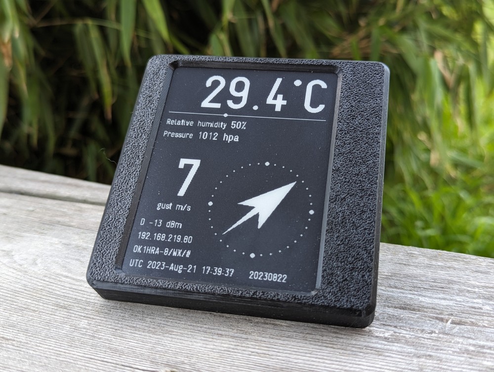
- Optional e-ink display
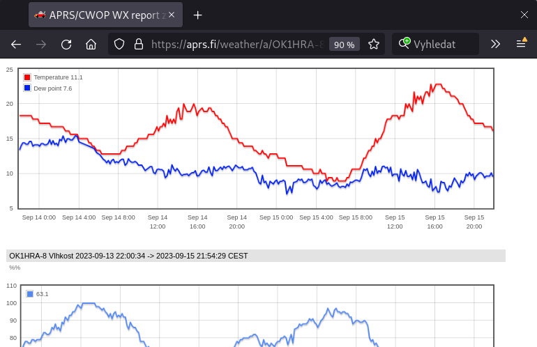
Instaled stations - OK1HRA-8 | OK1IRG-6 | OK1MKH-8
Features
- Measures values
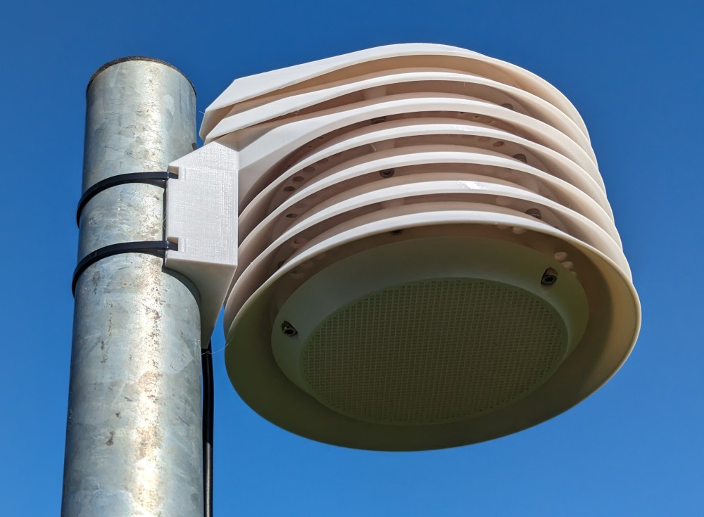
- Temperature (inside not exactly), external in sunshield
- Relative humidity
- Dew point calculated
- Pressure
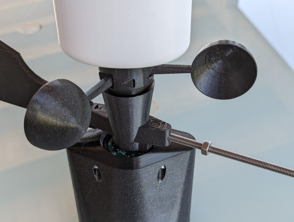
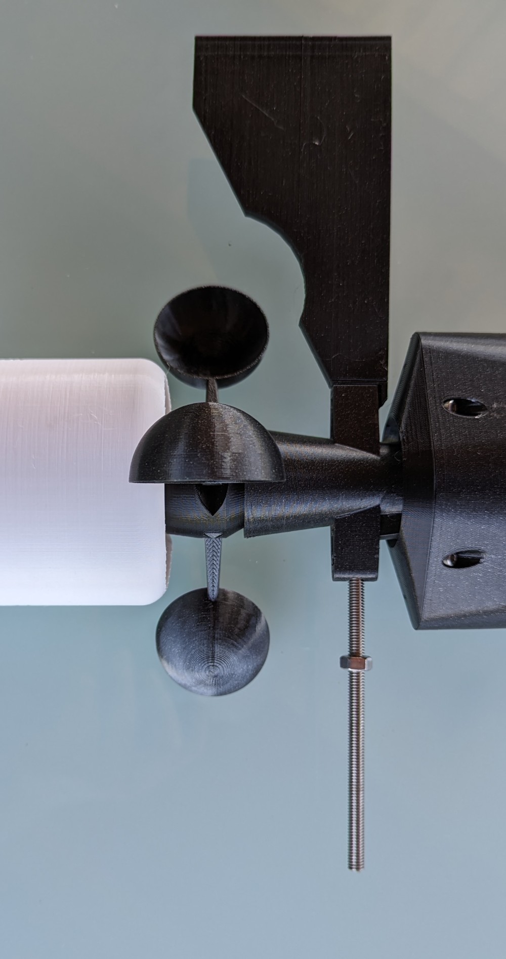
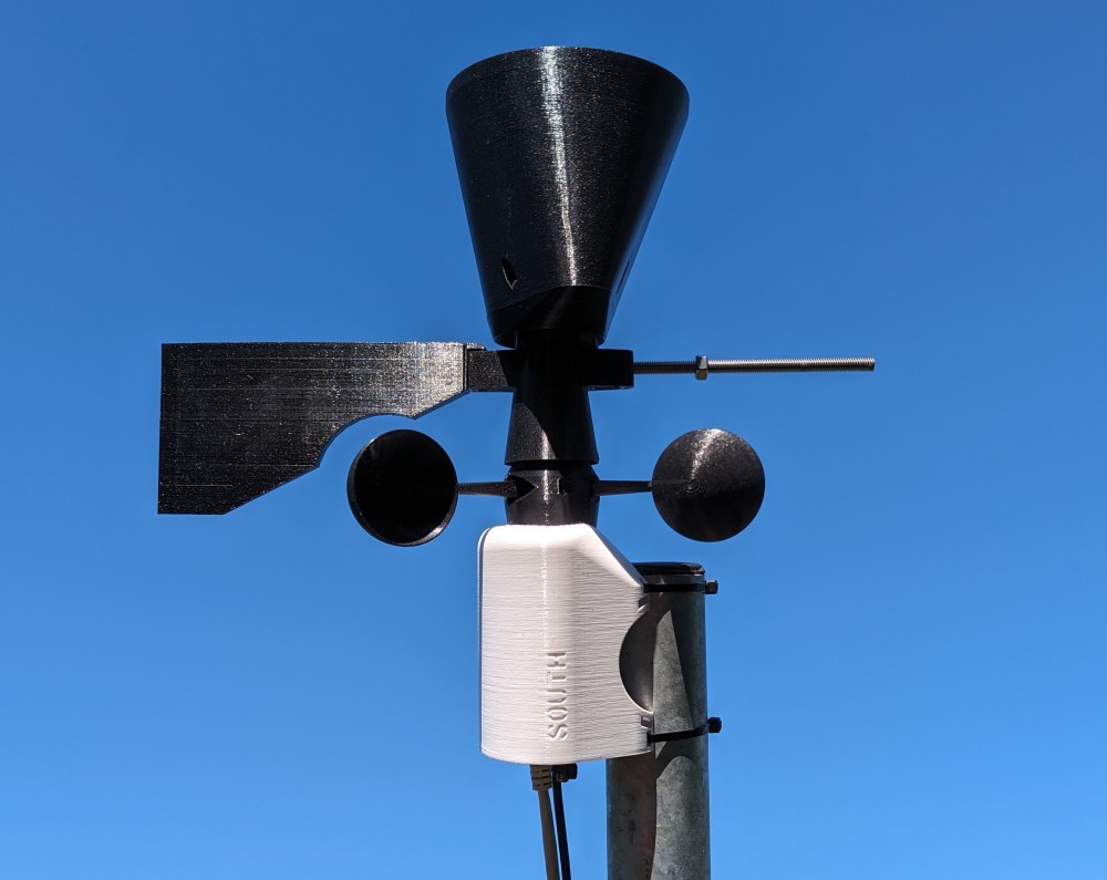
- Wind speed - with three blades
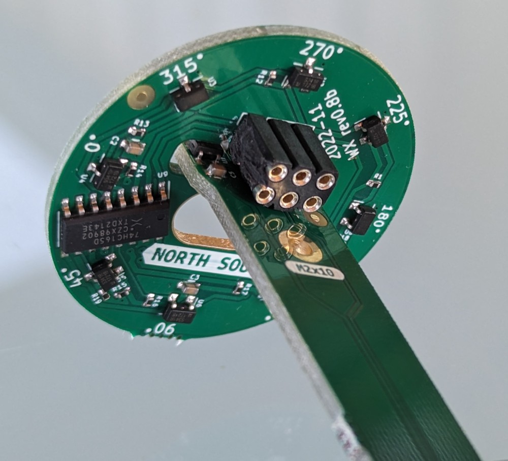
- Wind direction
- Rain with a resolution of 0.14 mm
- Ethernet RJ45 connection
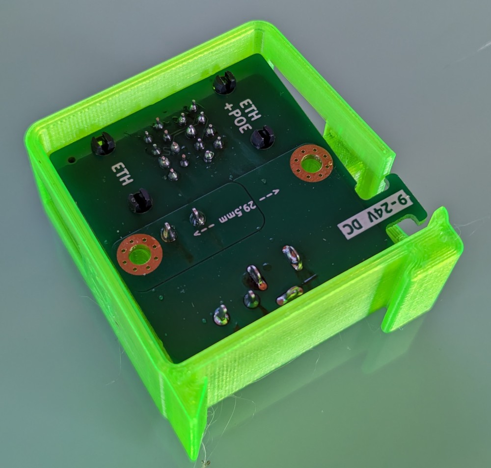
- Powered via passive POE with own adapter
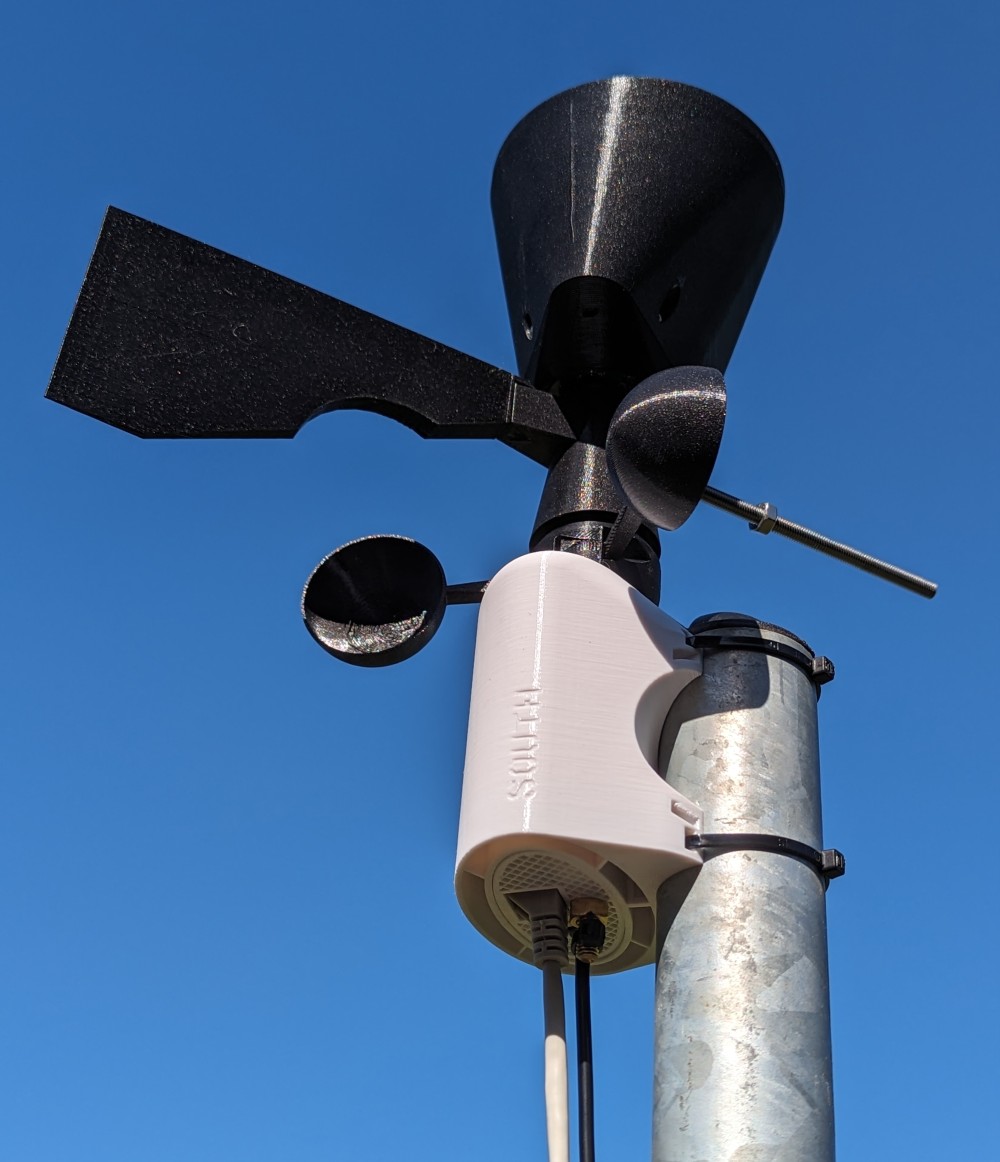
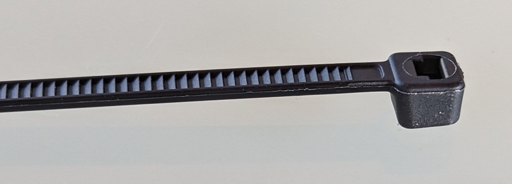
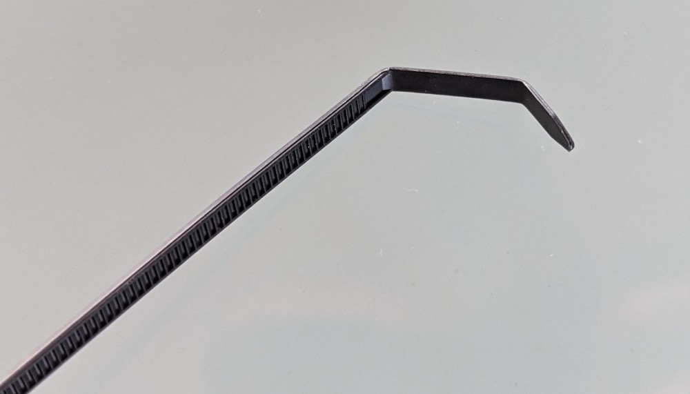
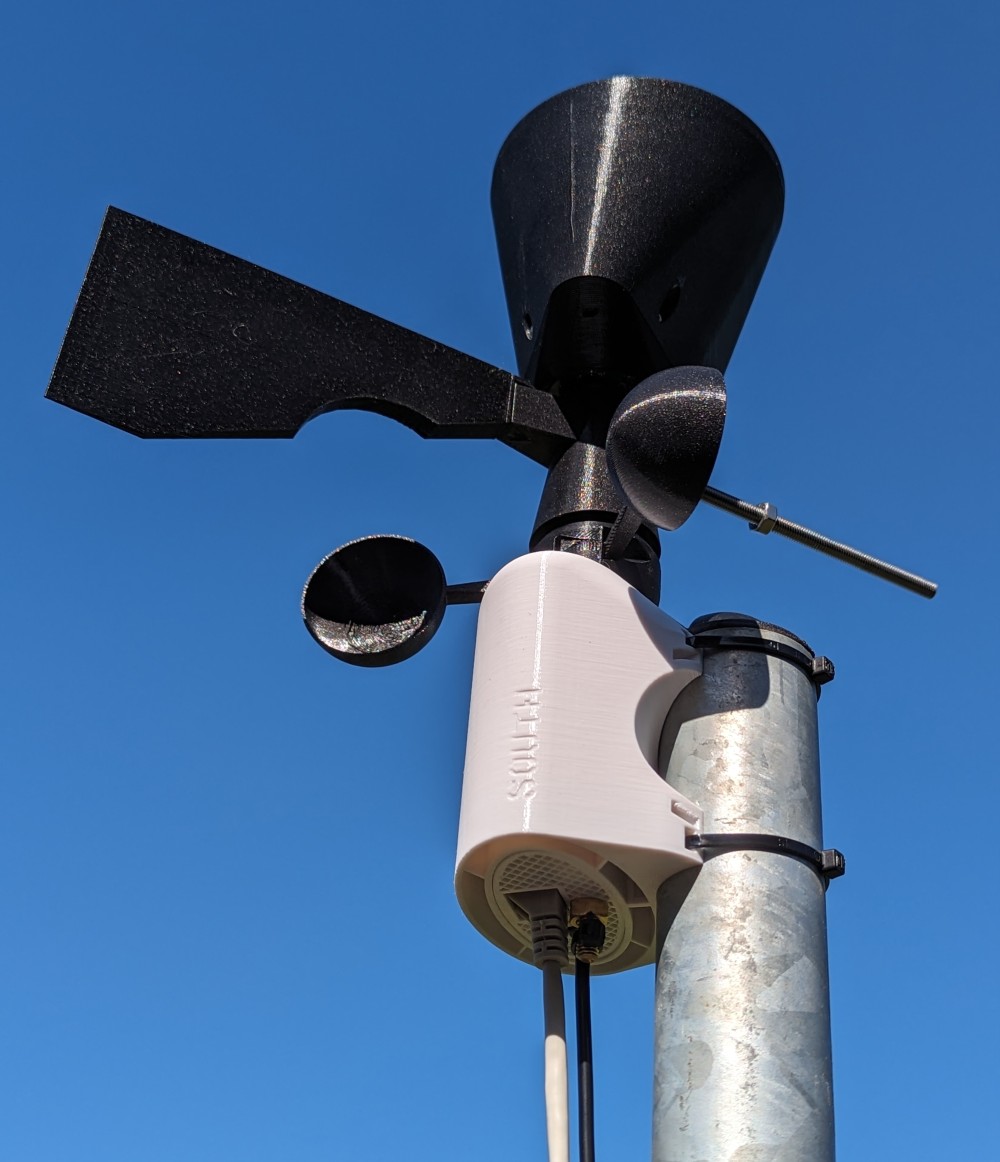
- Single mounting point installation with simple mounting with two plastic binding tapes
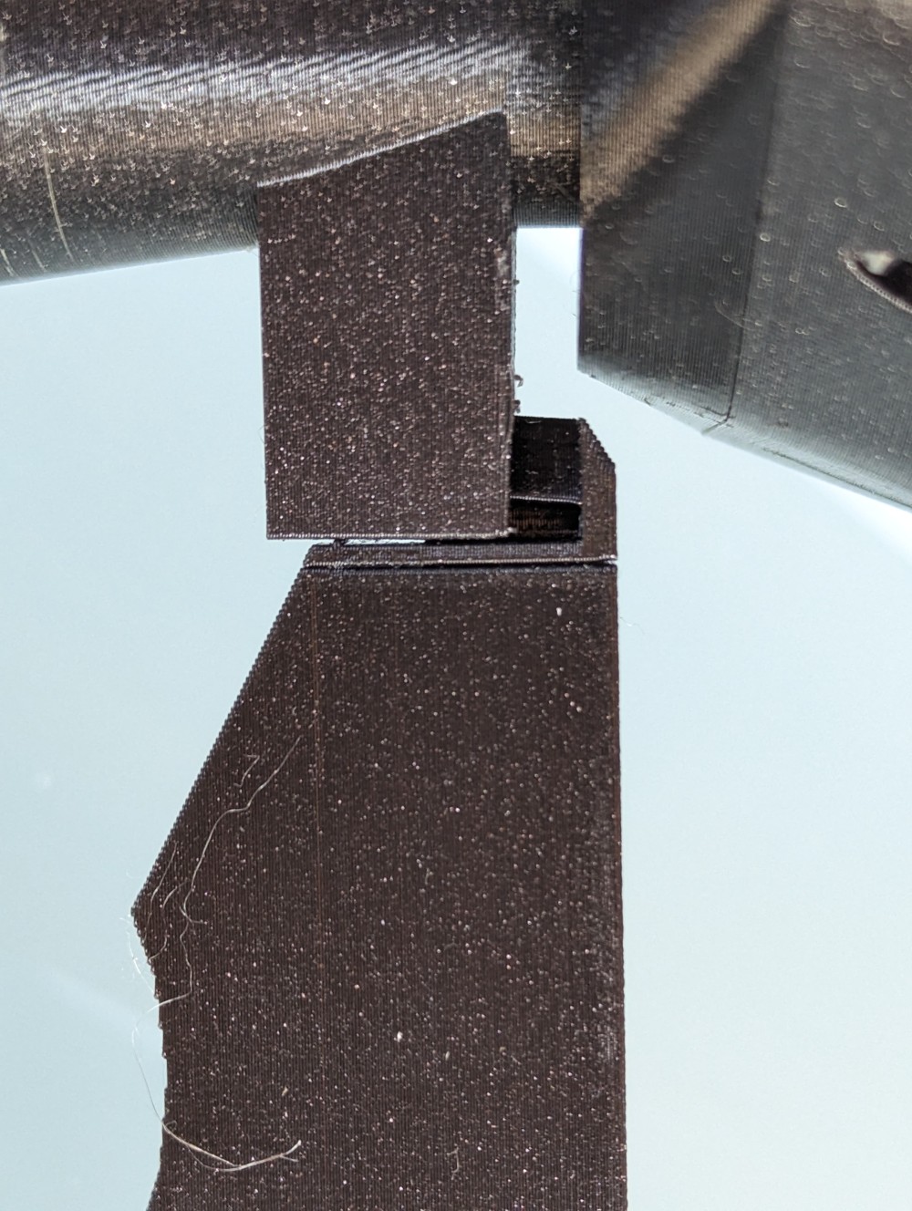
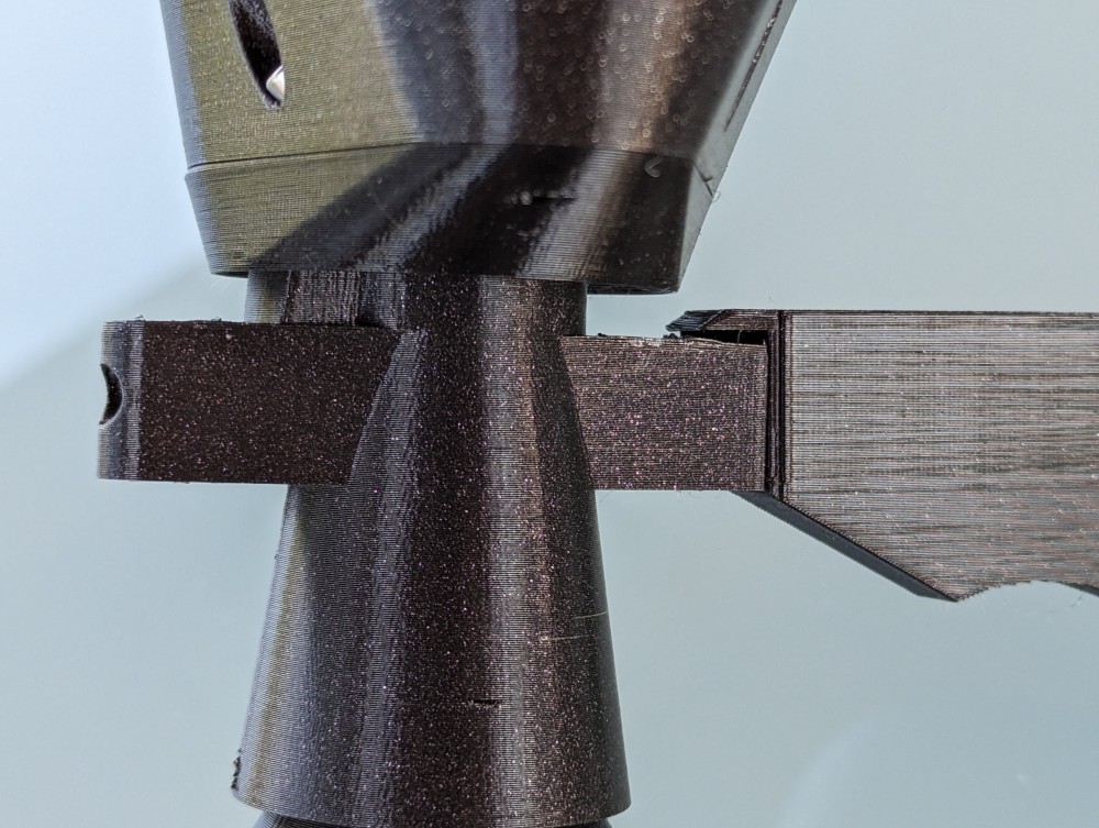
- Design supports an easy change of the diameter mounting tube, by replacing one 3D printed part (number 2).
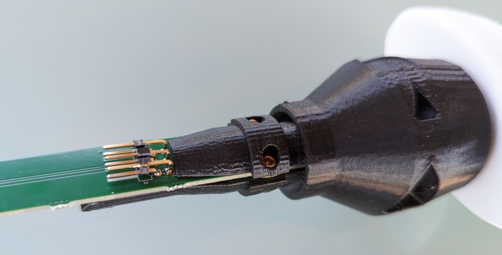
- Simply replace the vanes of the anemometer (if they are damaged) without disassembly
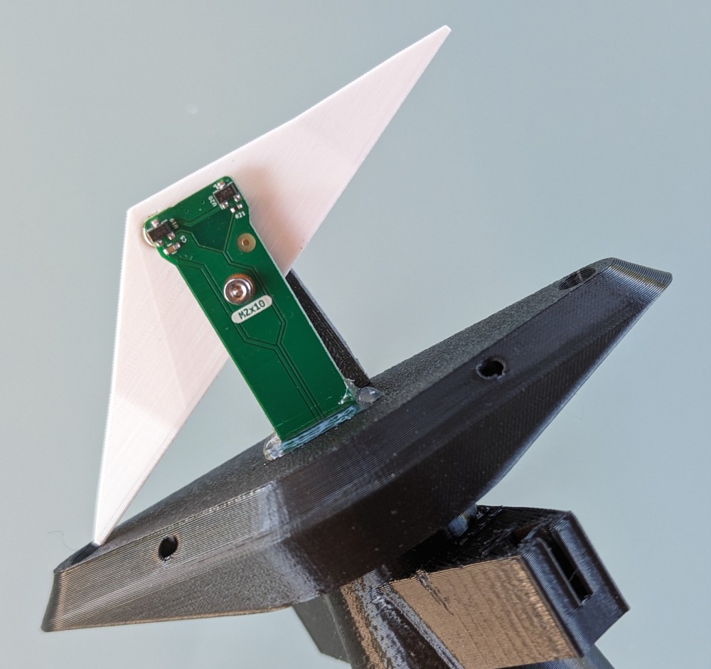
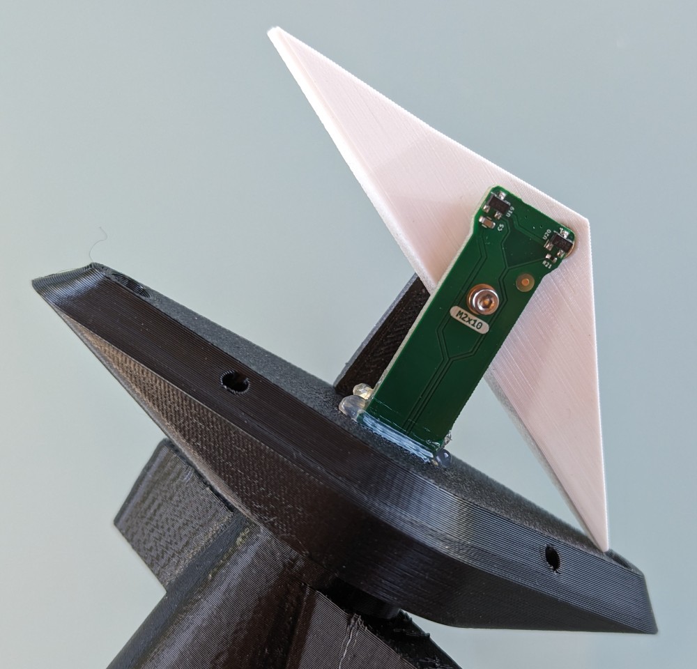
- Simply replace the paddle of wind direction (if they are damaged) without disassembly
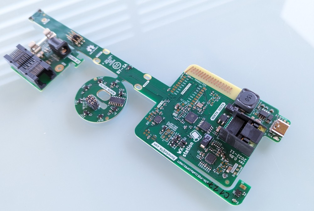
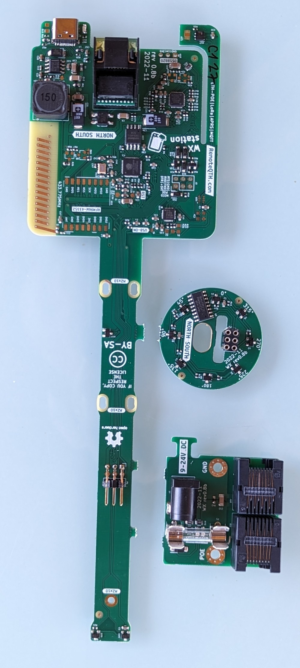
- No wiring, just fit two PCBs
- Completely 3D printed
- Publish data to MQTT
- Stores the maximum historically measured wind speed value with a time stamp to the eeprom
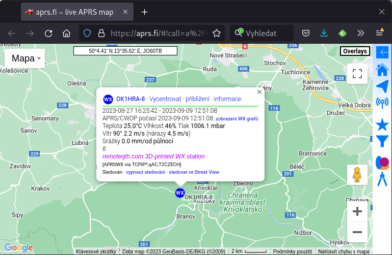
- Direct sending data to aprs.fi (if you have a radio amateur license)
- Setup via IP Telnet, with security using a hundred character security key
- Display of raw values of all internal sensors
- USB-C connector for read security key
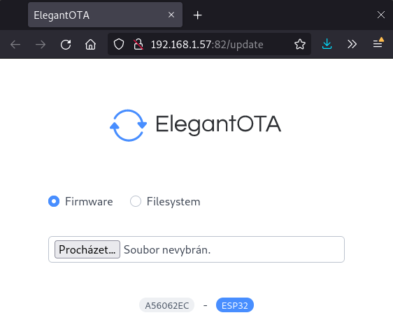
- OTA update via web interface
- Web MQTT wall, for simple debugging
- Hardware expandable by (they are not implemented in firmware)
- RFM96W-433S2 LoRa module (PCB antenna designed on main board), or other pin compatible module
- SHT30 sensor
- MS563702BA03 sensor
- ICP-10111 sensor
-
- Automatic detection of connection of external thermometer DS18B20 and switch to its values
BOM
3D printed parts
Download links in the source section.
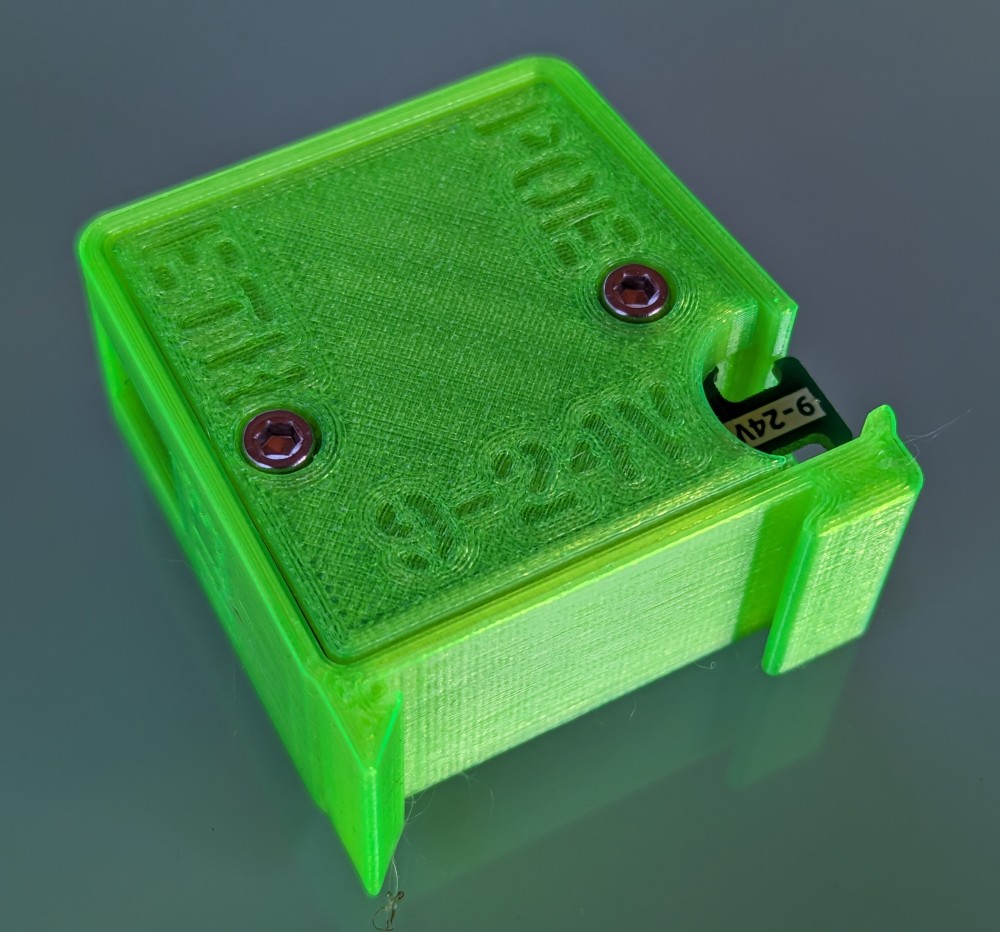
You can use 3D printing to order, for example at mirex3d.cz - don't forget to specify the diameter of the mounting pipe.
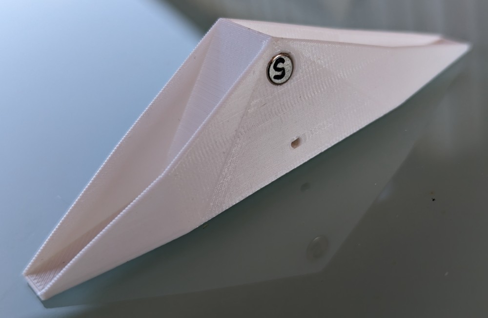
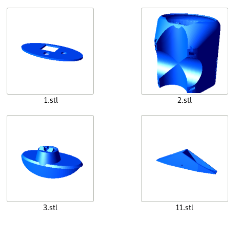 | Printed parts 200g White PETG filament White due to reduced overheating from the sun light Part number 2 is exported for a 42mm diameter mounting tube. If you need a different diameter, change the value in the source code, then change the part to number 2. Open the file in OpenScad, and follow the instructions. After printing, remove the supports and remove the strings using hot air | 4 pieces |
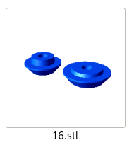
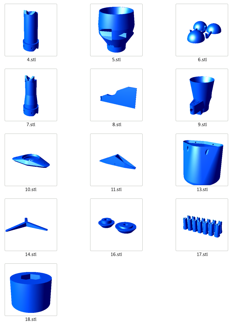 | Printed parts 250g Black PETG filament Black due to the absorption of sunlight, it melts the winter ice as soon as possible Number 14 is an optional stand for the chair Number 16 is a necessary part for pressing the bearings Number 17 is optionally scaled internal parts of the bearings to find the optimal tolerance, if necessary Number 18 part for formatting bearings After printing, remove the supports and remove the strings using hot air | 13 pieces |
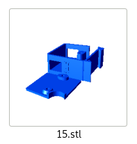 | Printed parts 25g Transparent PETG filament due to the show of the LED in the POE module After printing, remove the supports and remove the string using hot air | 2 piece |
The other parts
Tools
Assembly manual, step by step
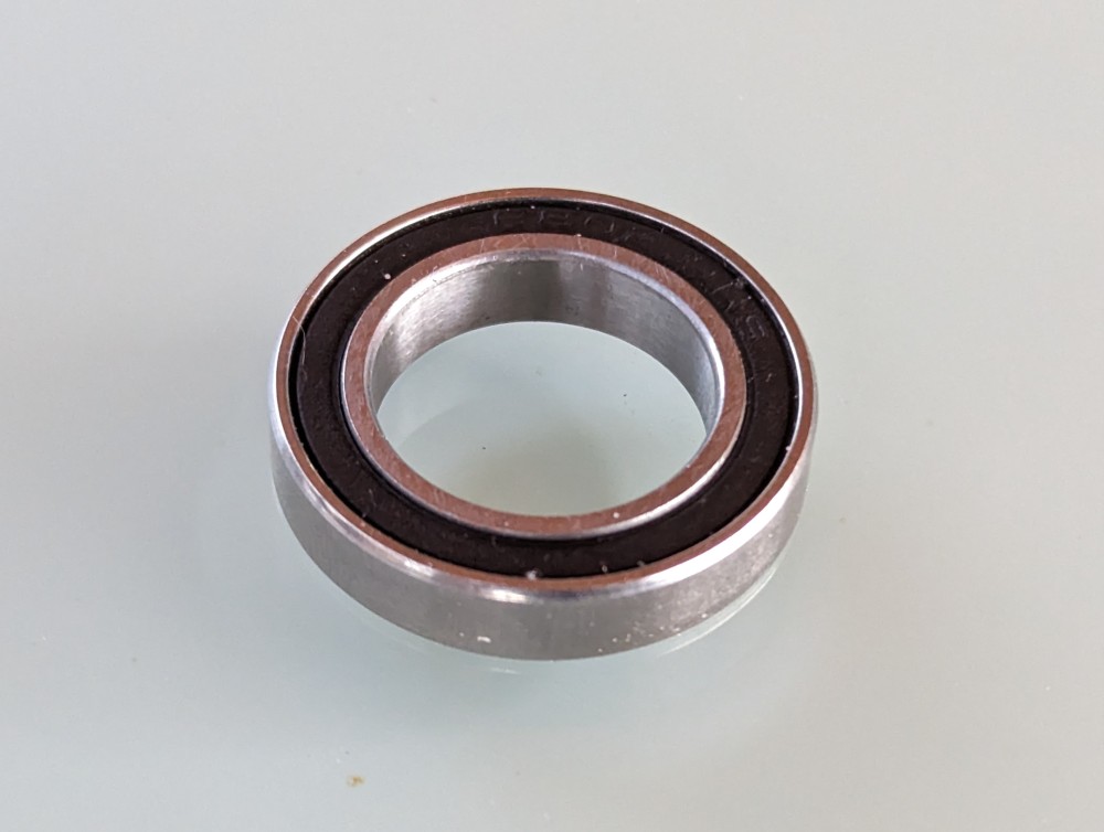
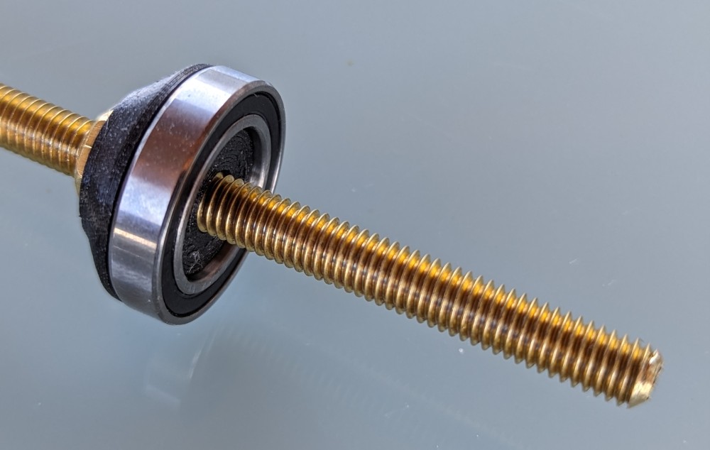
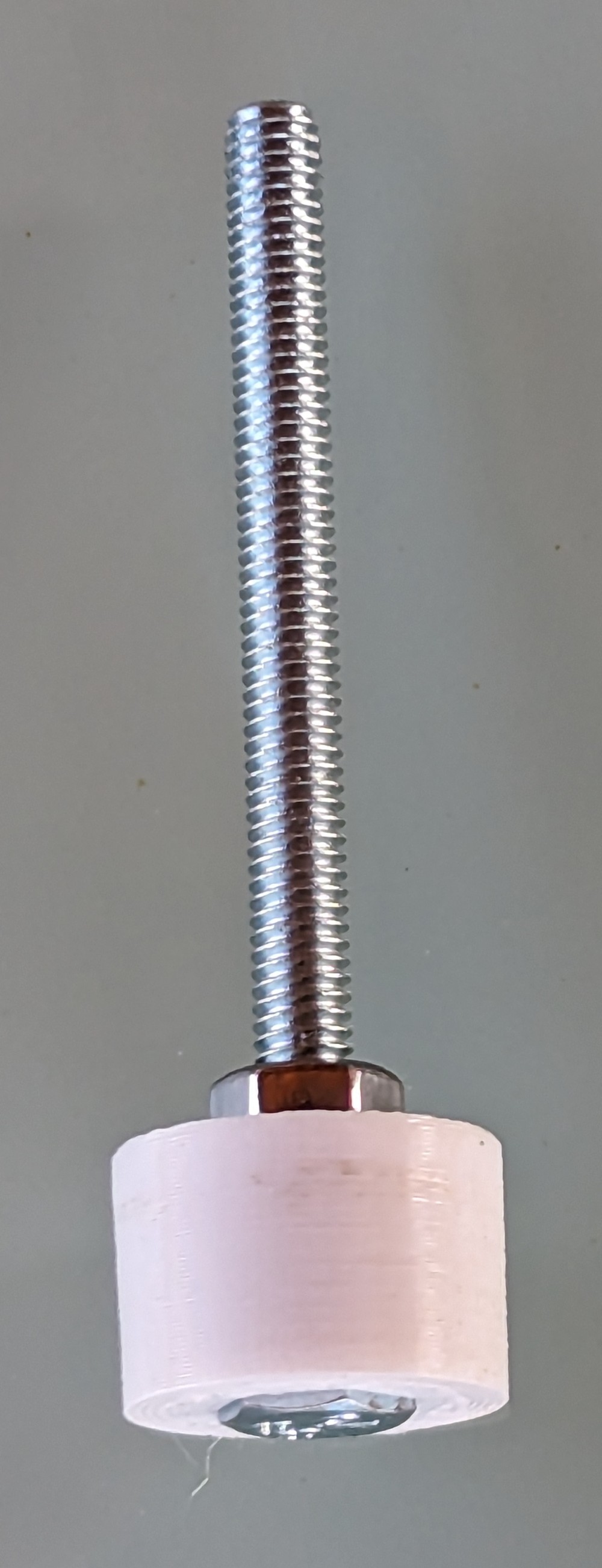
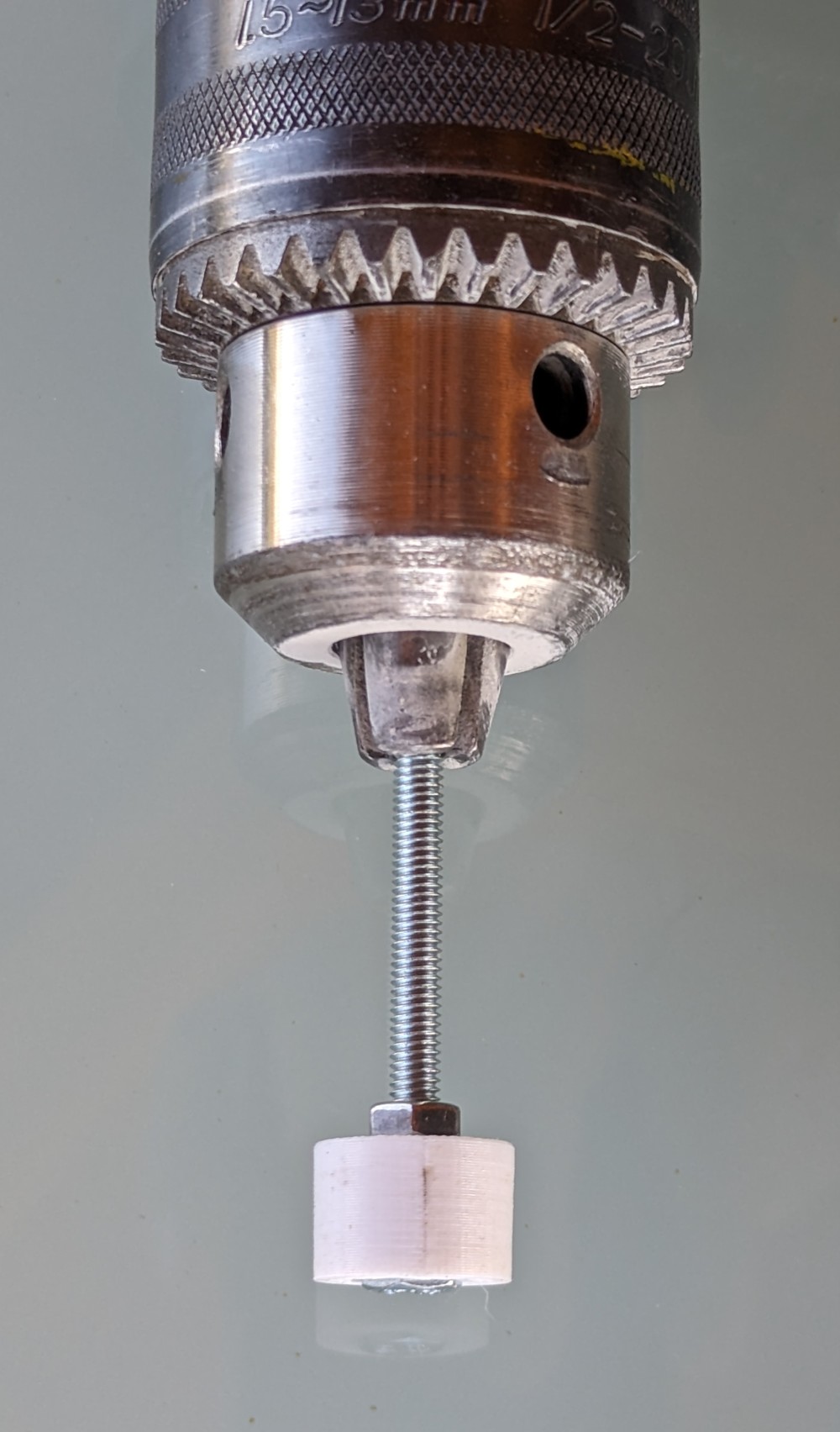
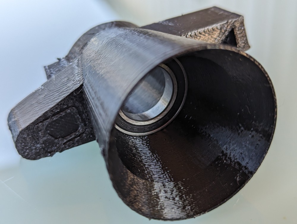
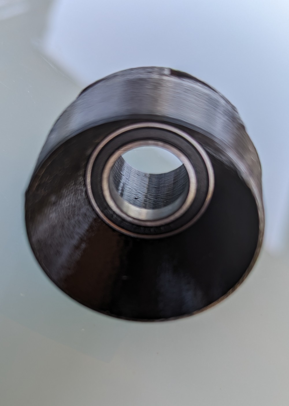
- Disassemble the entire tool, the bearing should be pressed inside the part.
The new bearings have considerable resistance. Over time, it will decrease during rotation.
This process can be accelerated with a simple tool, with which we spin the bearing for a few minutes with a drill.
-
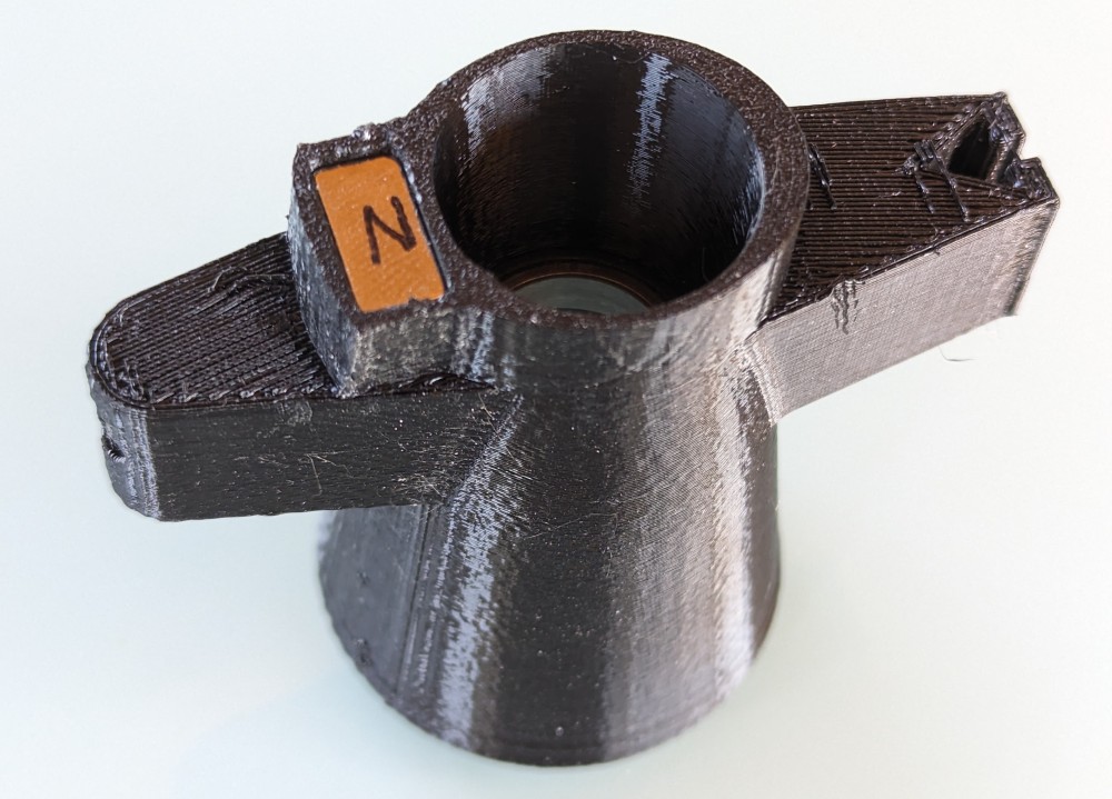
- Using the compass, or with other methods (hanging on a thread, floating on water…)
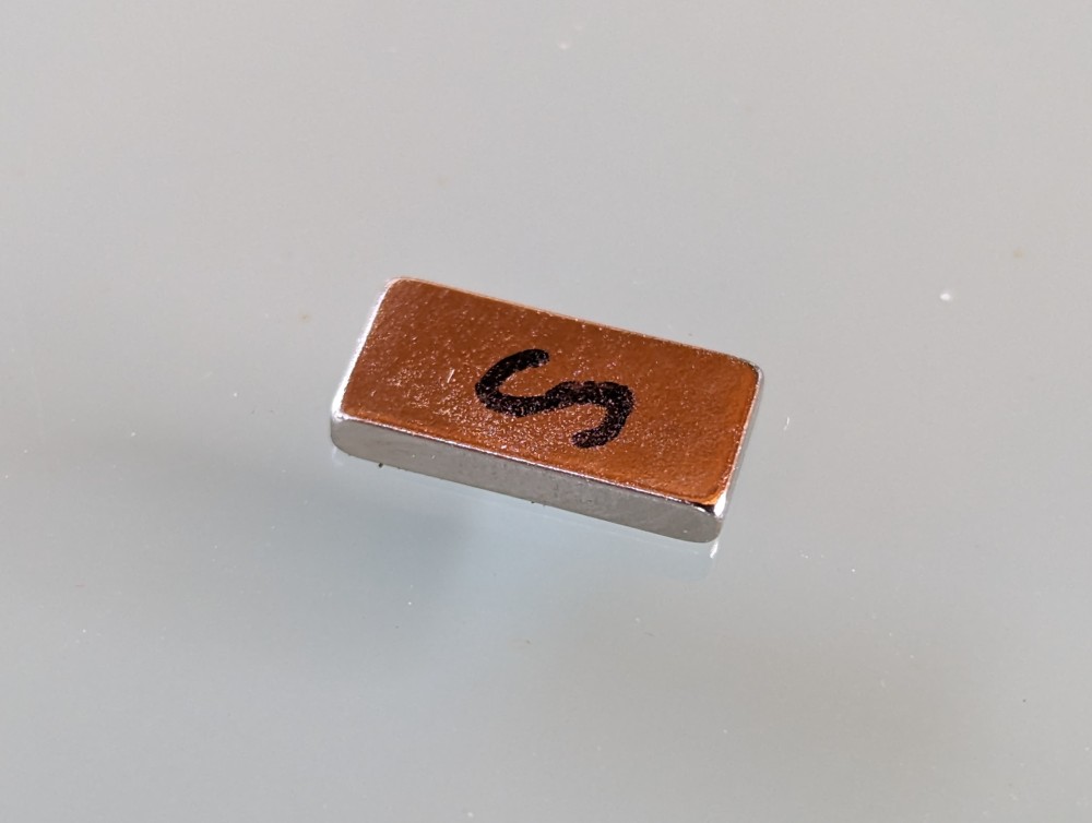
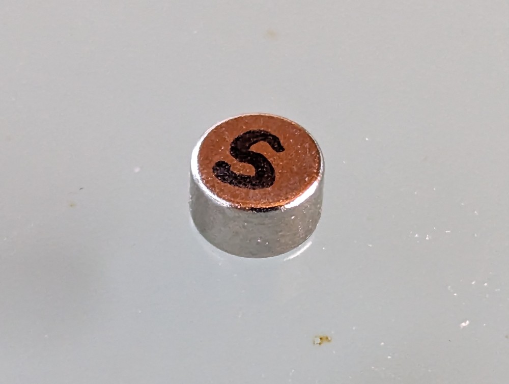
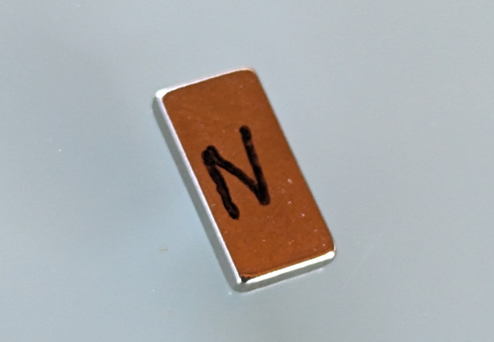
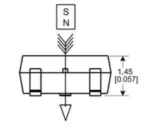
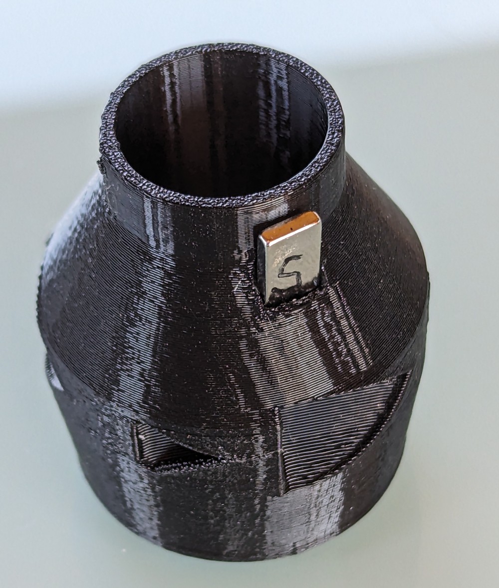
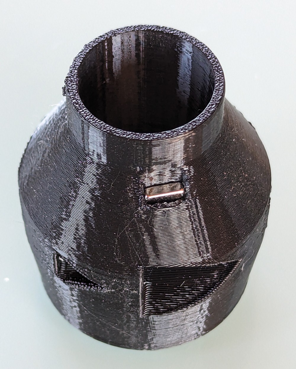
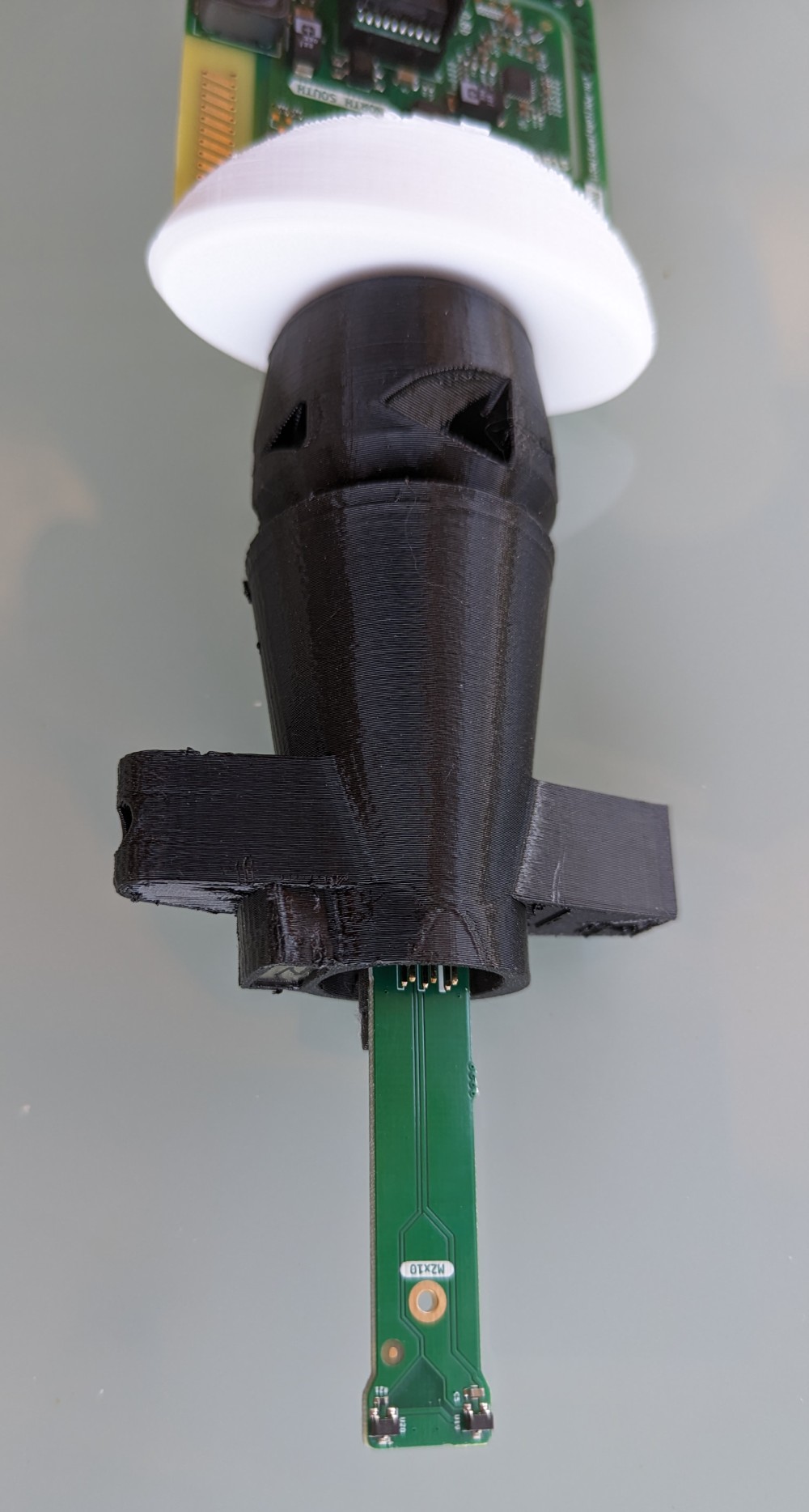
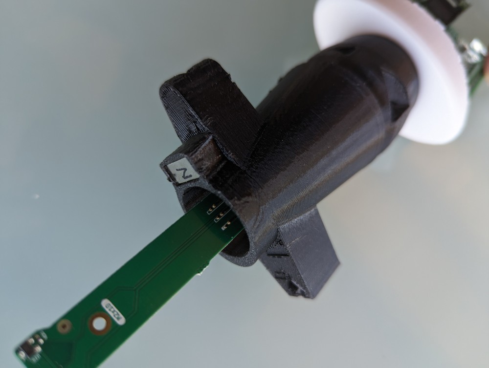
- By attaching a magnet to the hall probe on the main PCB WX of the station, the probe responds to the N pole
- Connect to the weather station using telnet
- By default, the sensor is in the RpmPin 1 state
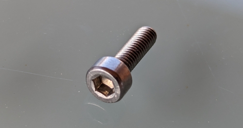
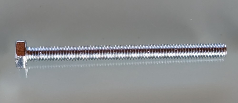
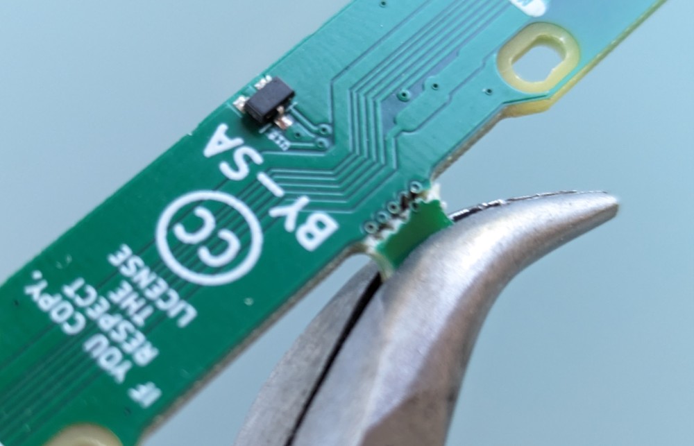
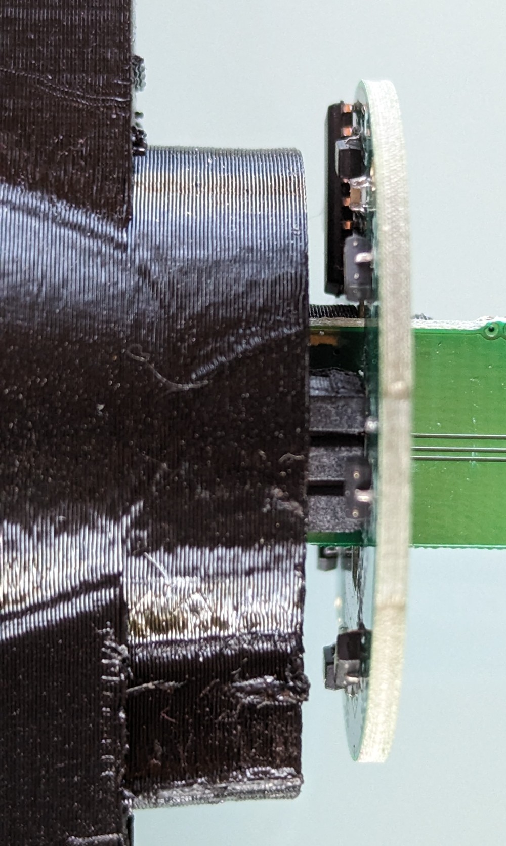
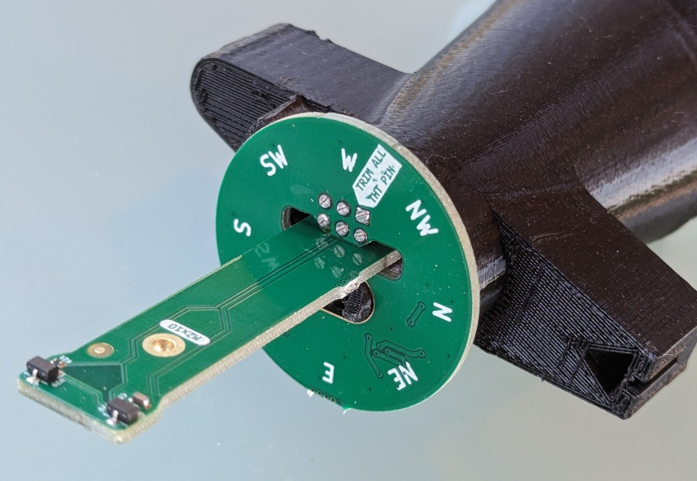
- Using two M2 x10mm screws, attach the cradle to the main plate and plastic bracket number 12. The screws must remain loose so that the cradle can rotate freely. The ideal situation is when, by moving the cradle in the axis of rotation, the cradle does not touch either side (the PCB or the supporting plastic part.
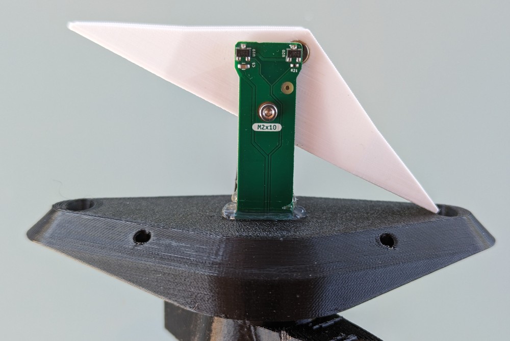
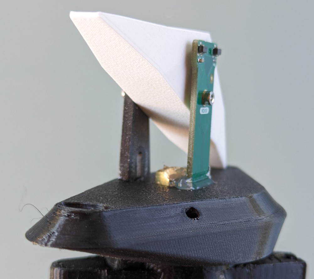
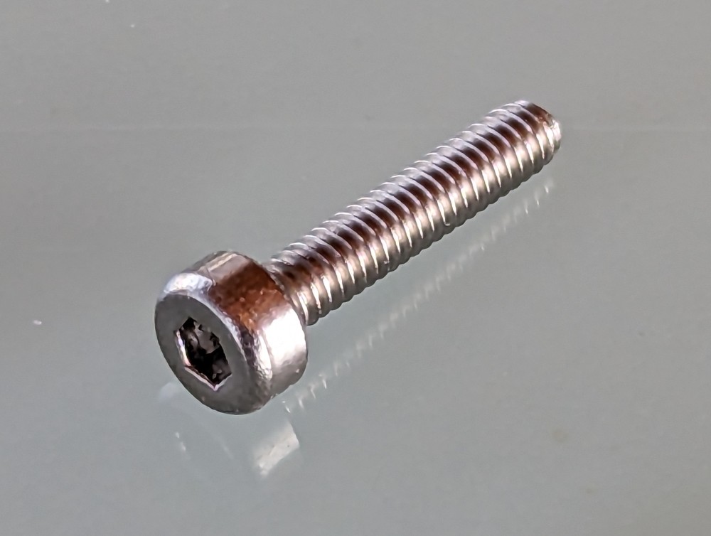
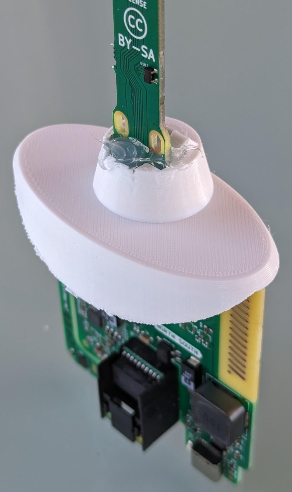
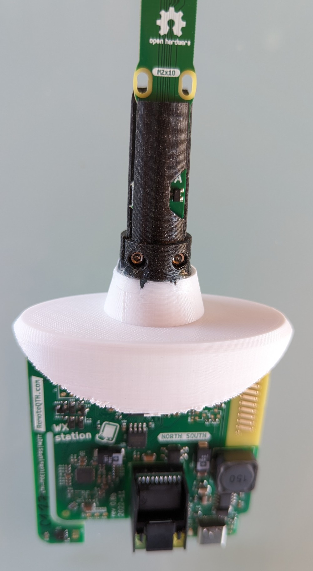
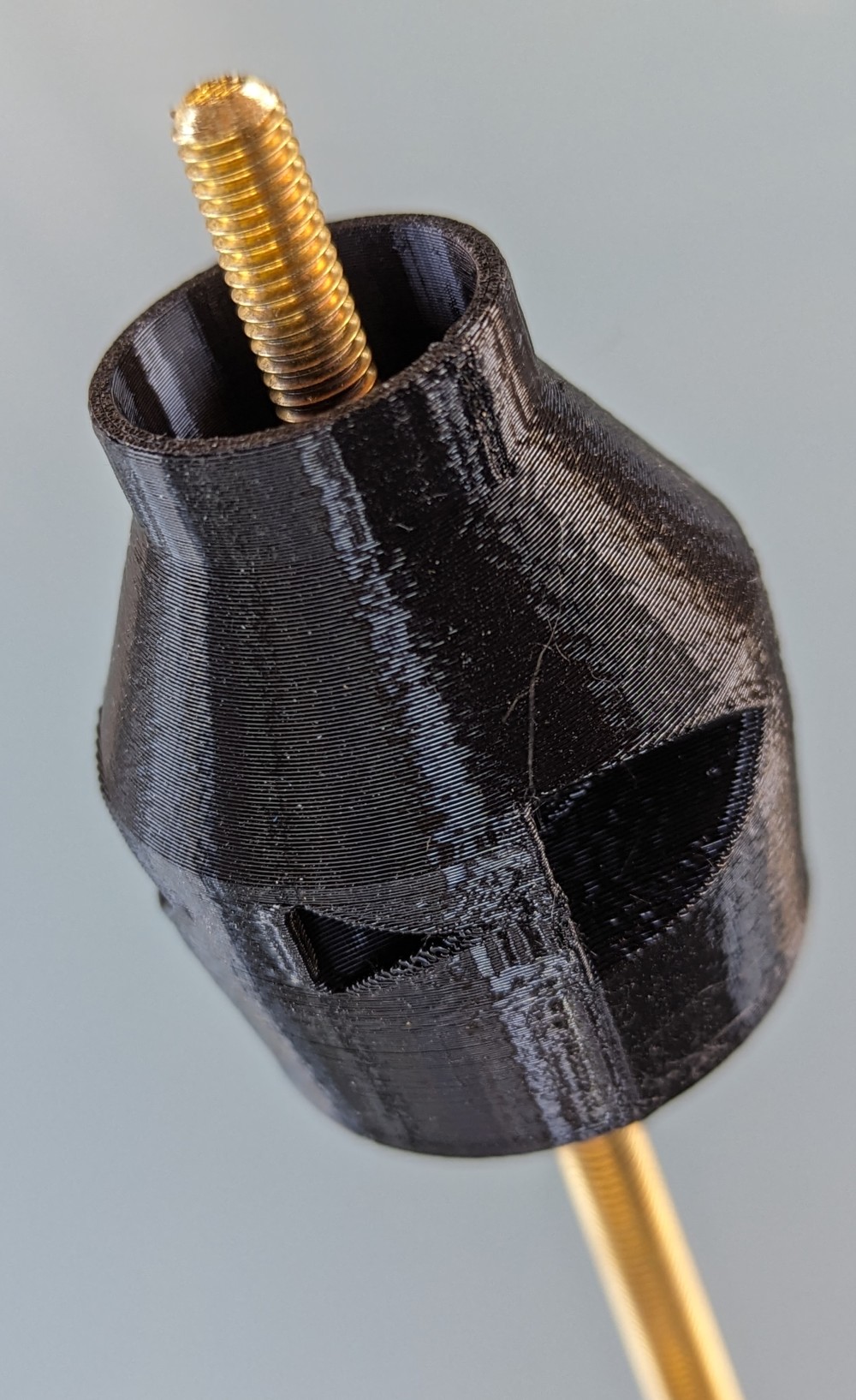
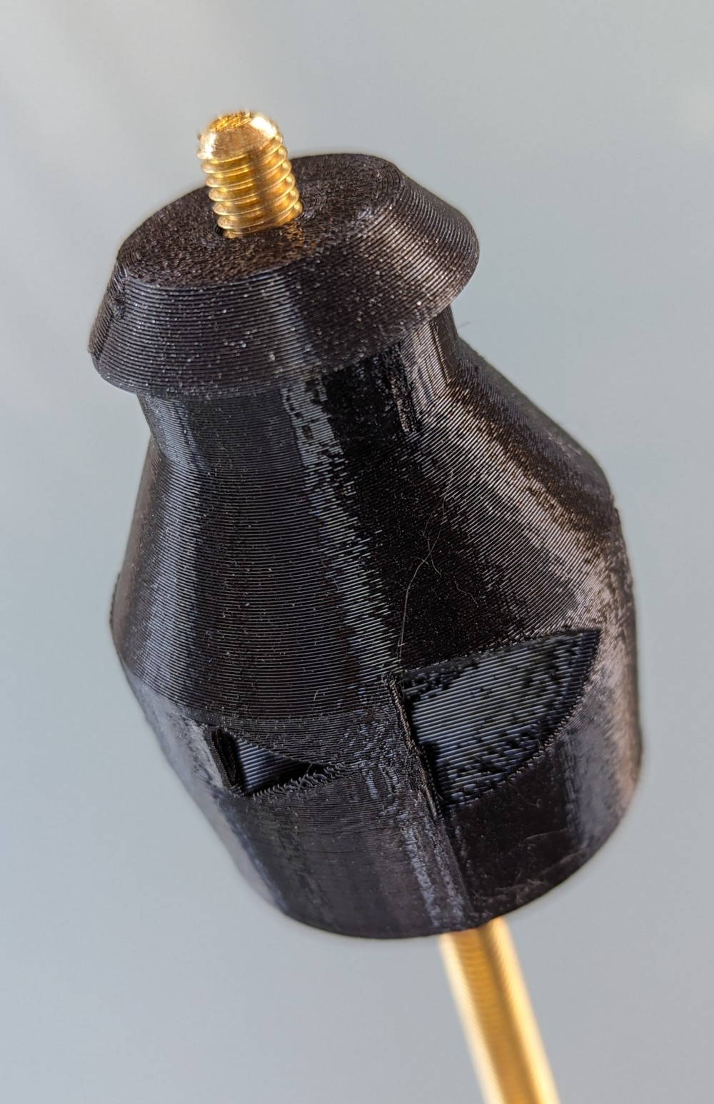
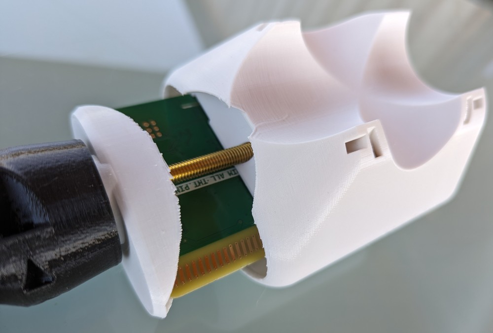
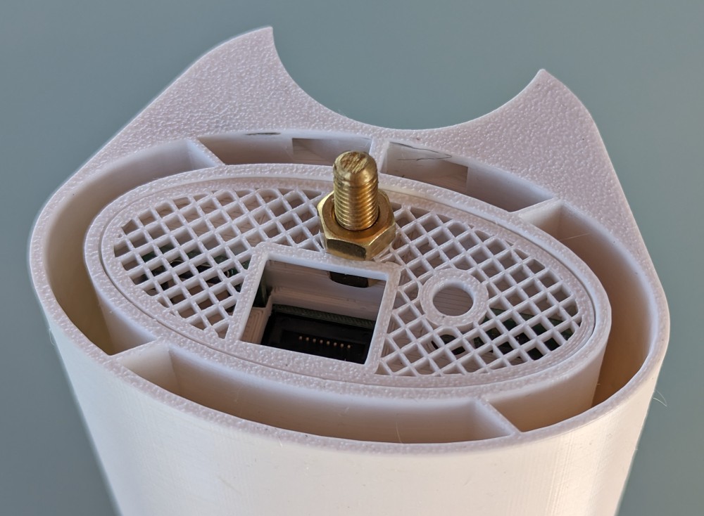
- Before putting on the 3D printed part number 13, we remove the strings from its inner part with the help of hot air. Strings are thin and hard to see, but they can prevent the cradle from tipping over inside. Then we screw the part to the main structure using four M3 x10mm screws. Attention, we do not tighten with force, the screws are only in conical plastic holes, without metal nuts.
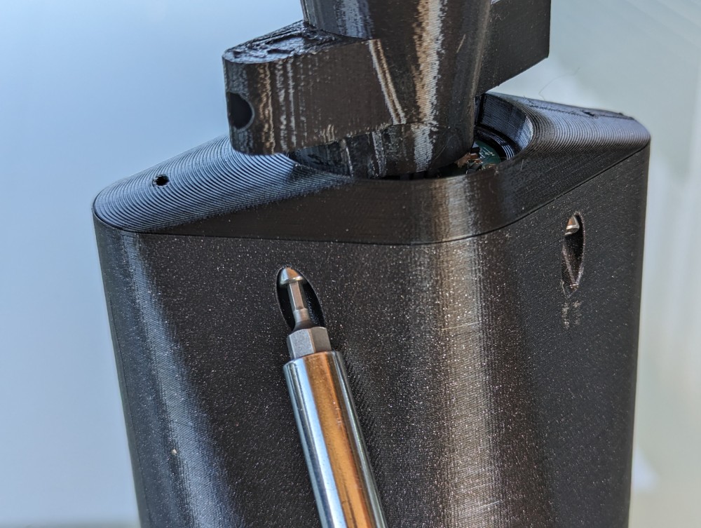
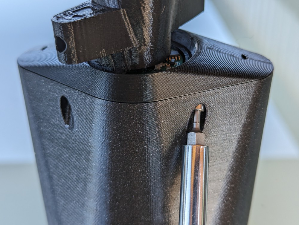
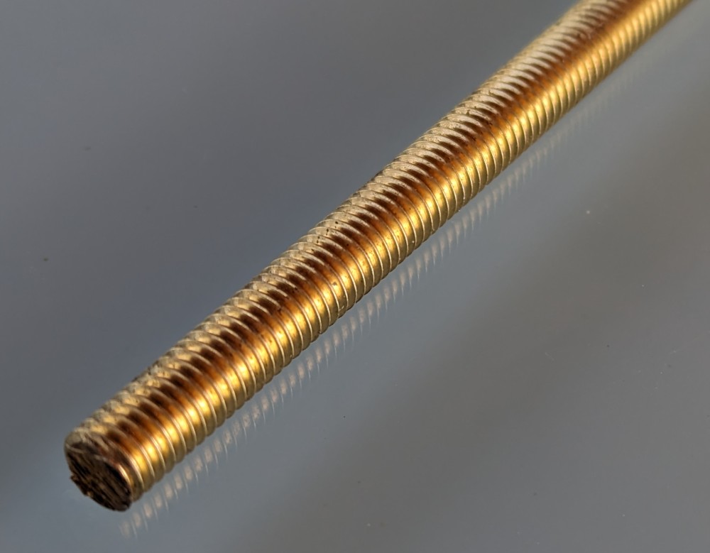
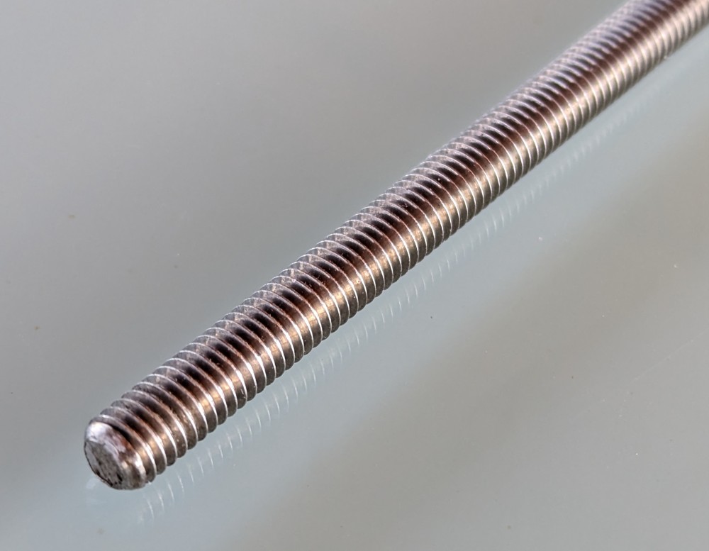
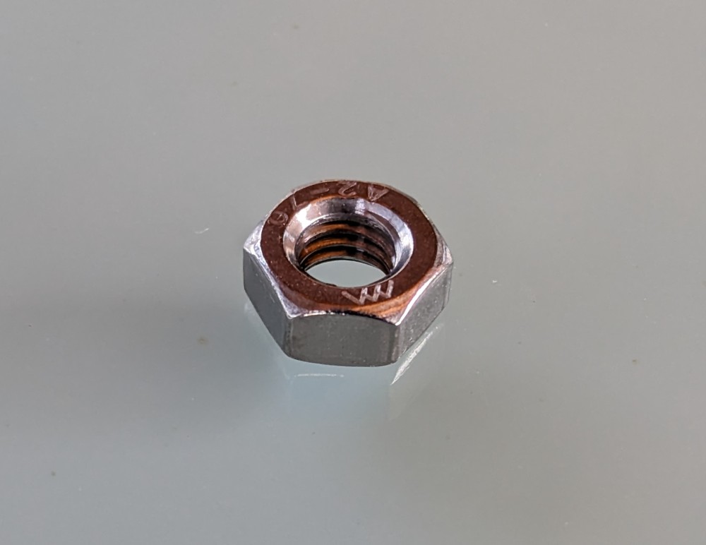
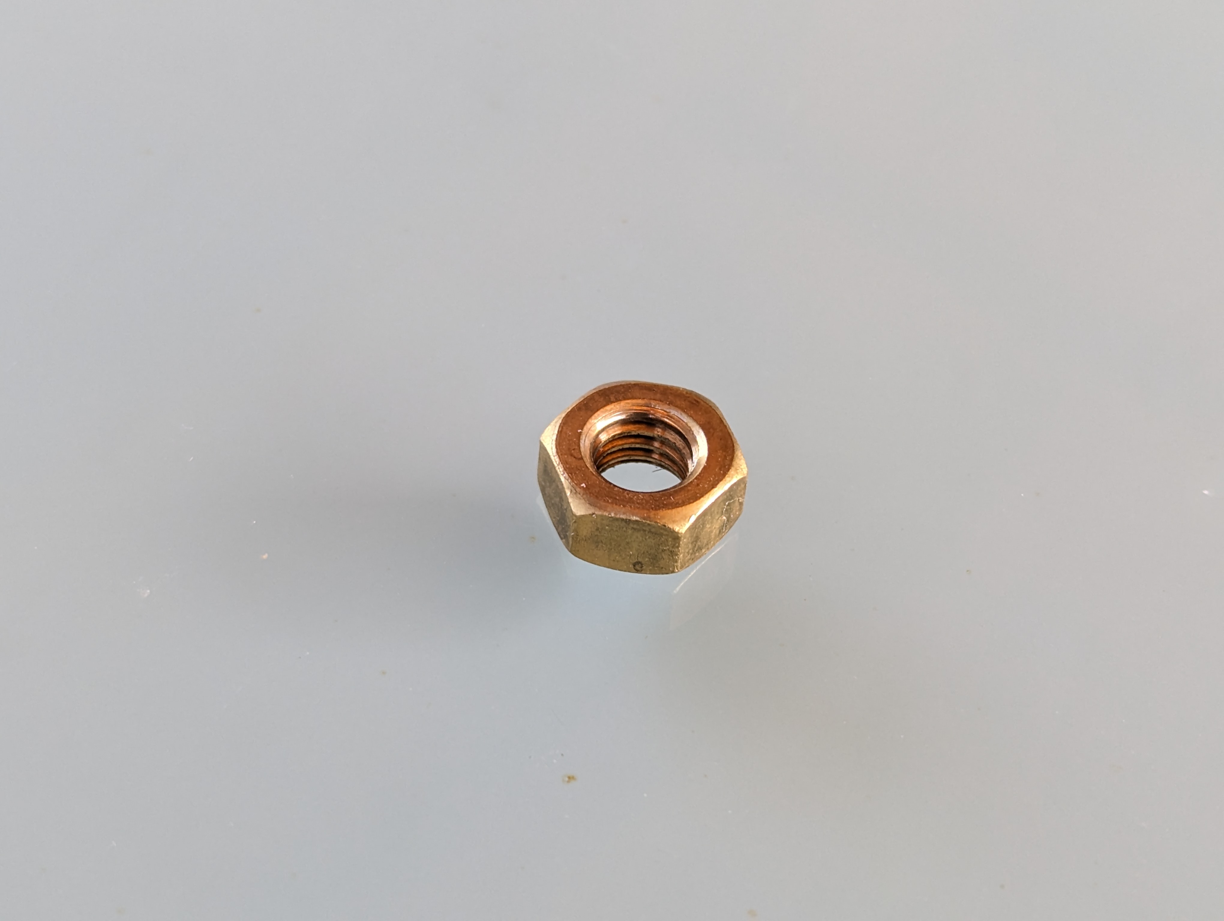
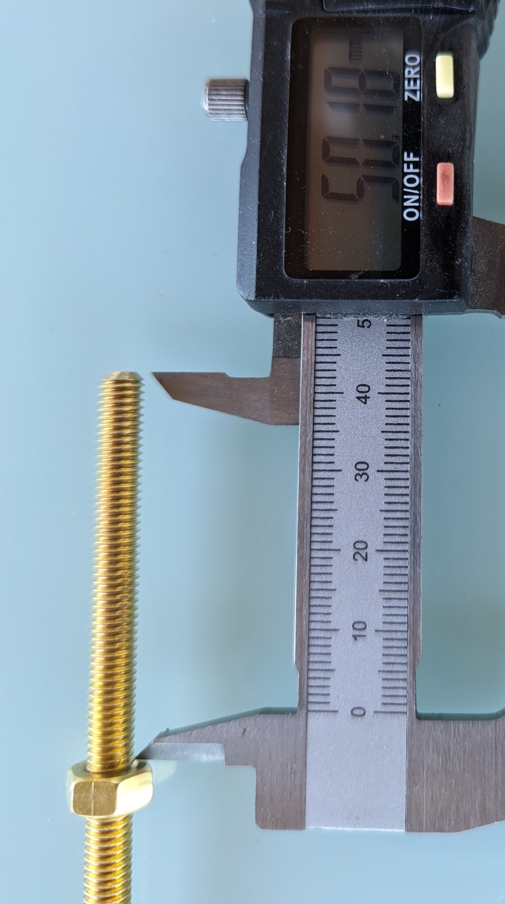
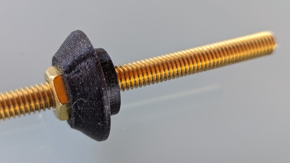
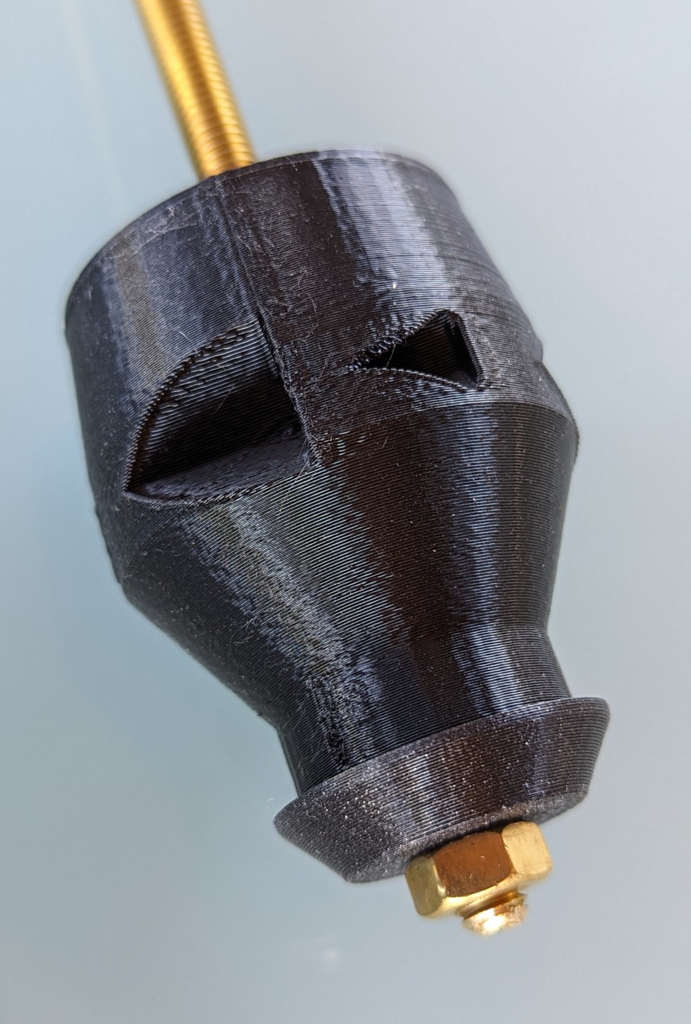
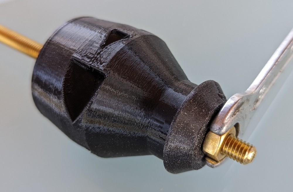
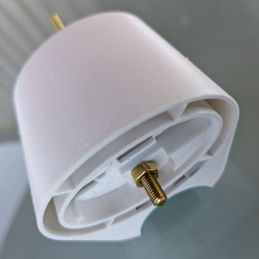
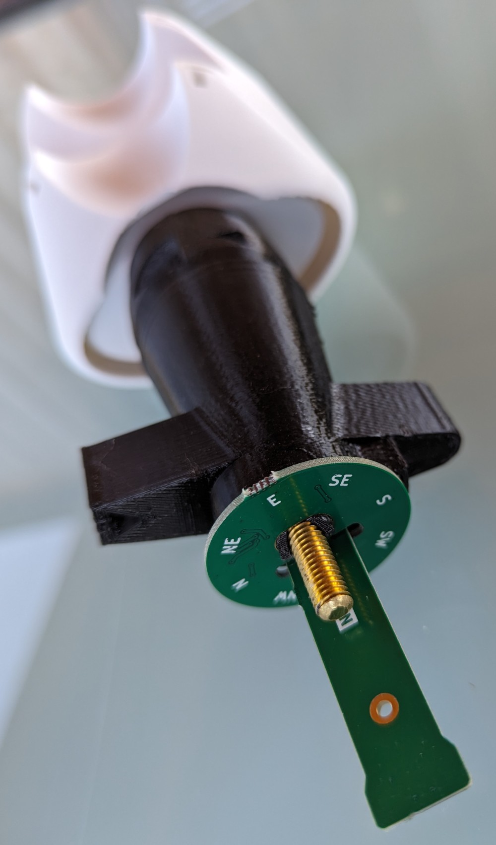
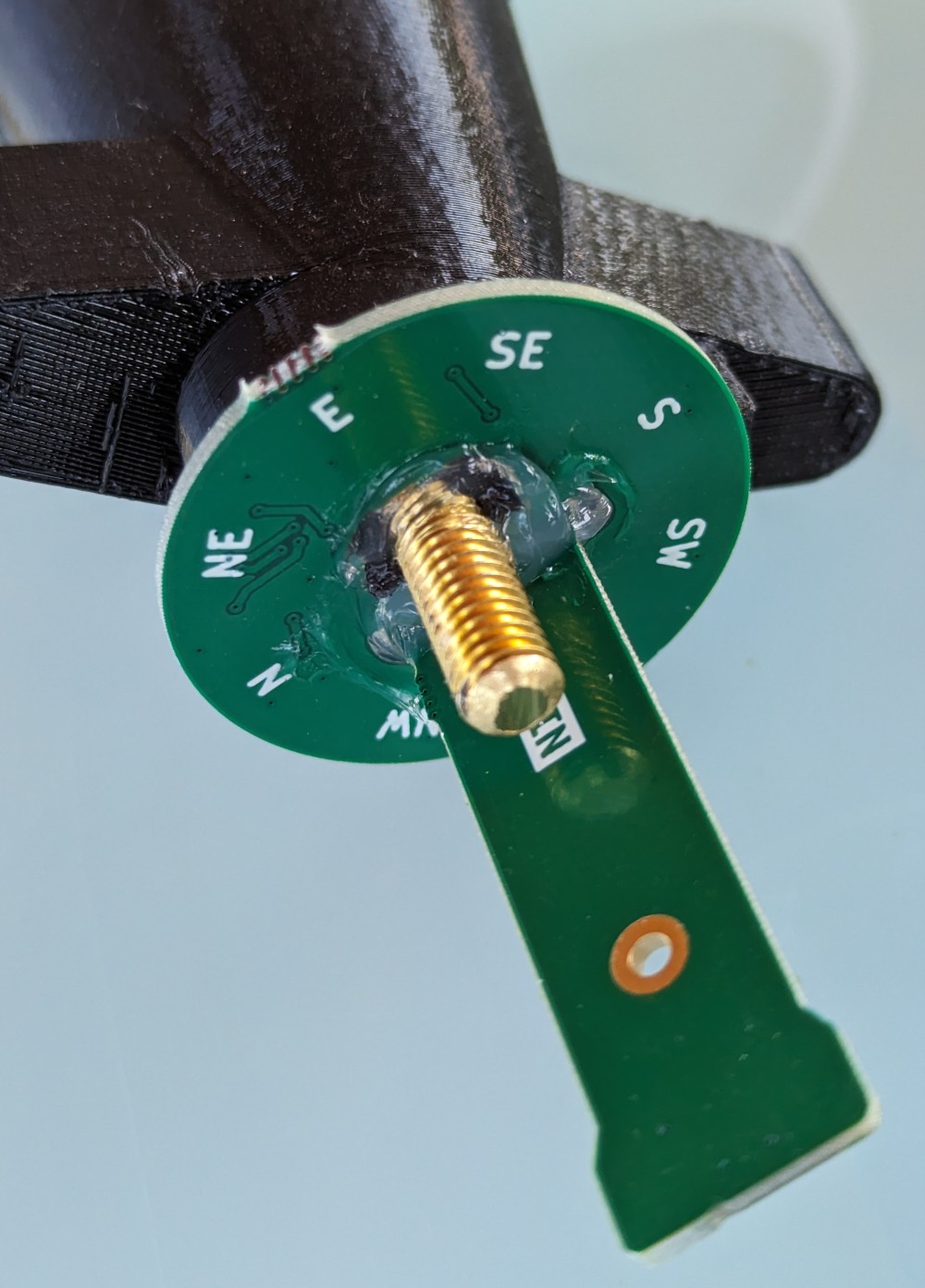
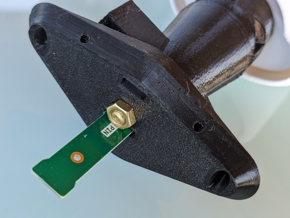
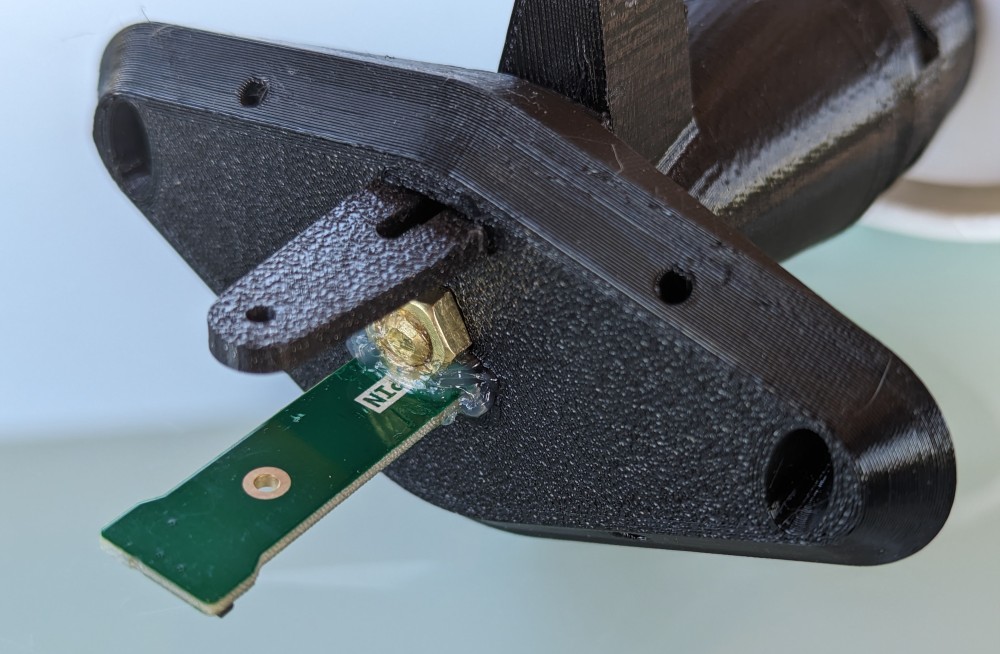
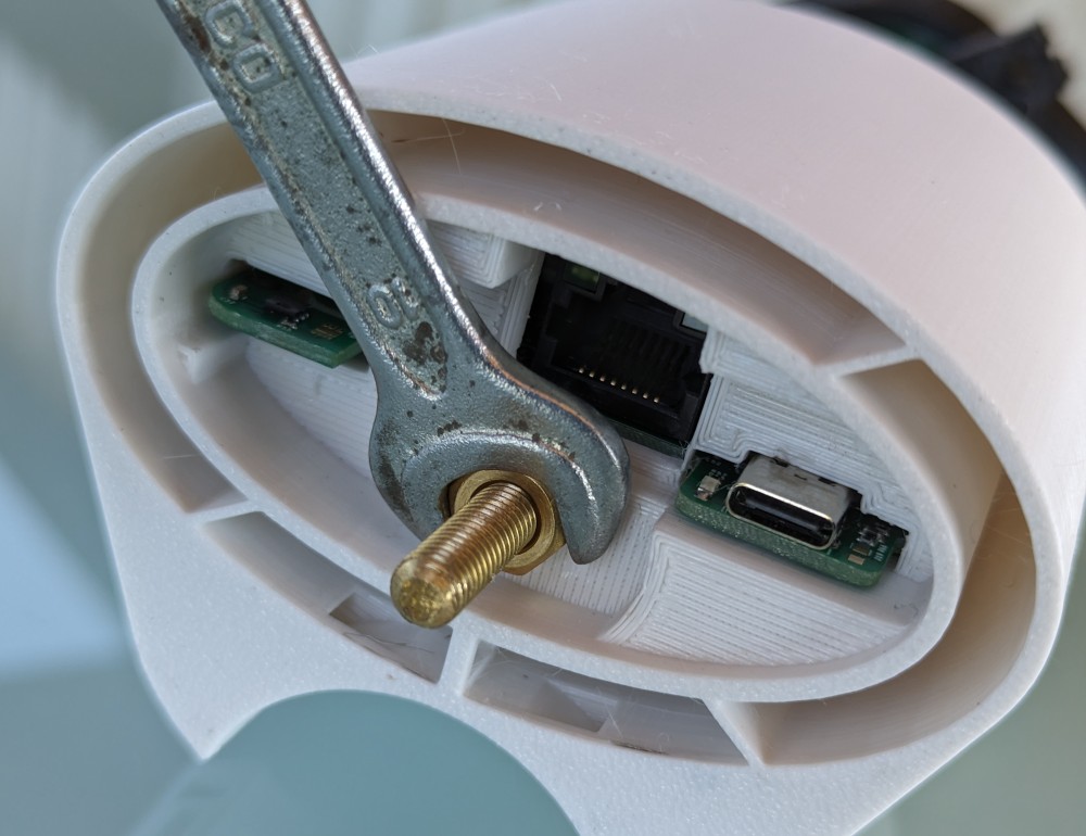
- We screw in the stainless steel threaded rod from the opposite side until it starts to resist, which is the end of the plastic taper hole. Then we screw the stainless steel nut onto it, by screwing it along the threaded rod we balance it so that it remains in a horizontal position. Finally, secure the mother with a bit of silicone sealant.
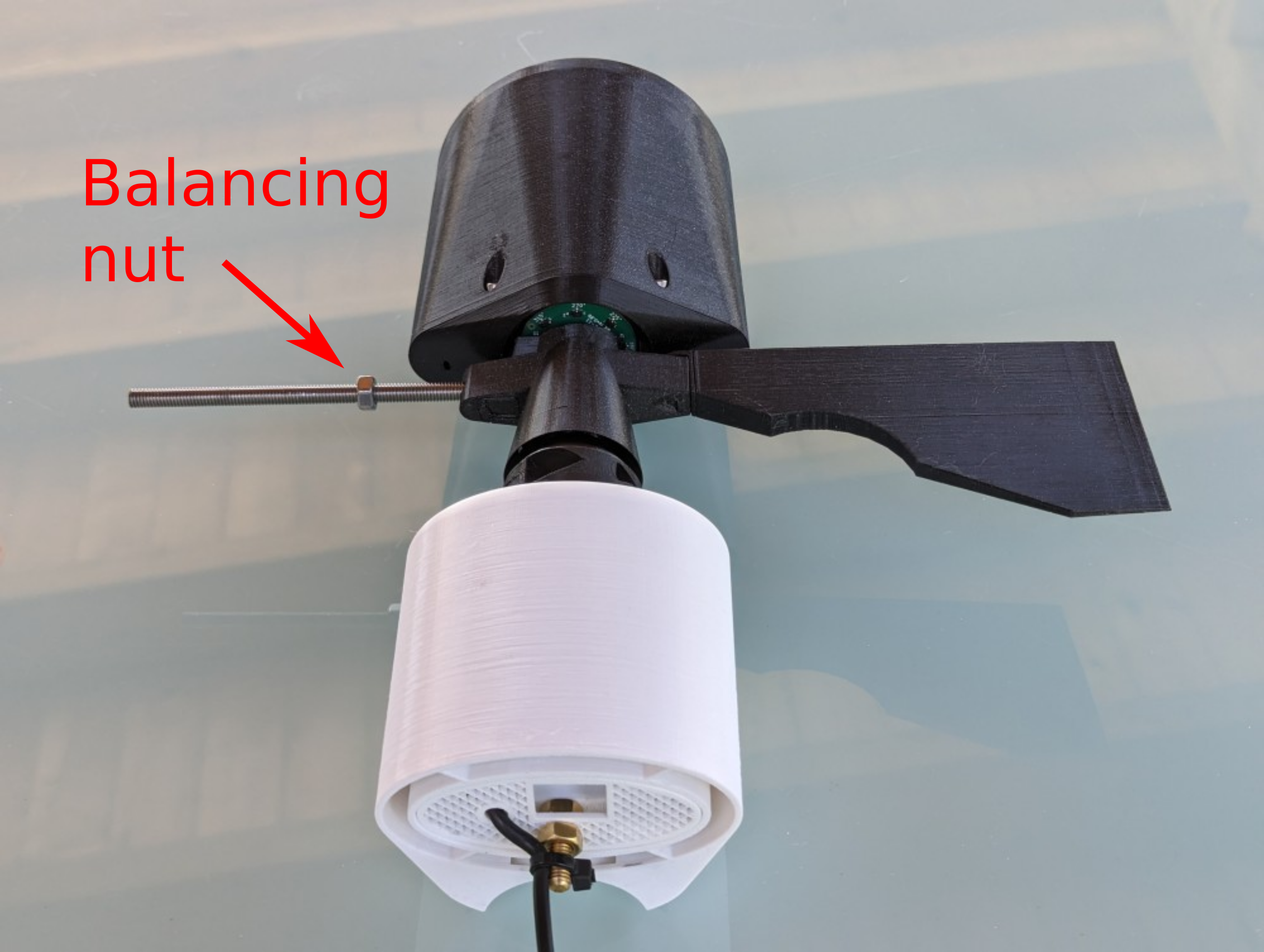
- You can optionally continue
- Connect External thermometer DS18B20
Connection using telnet and settings
How to connect
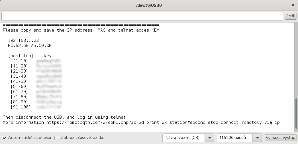
Reading the access key
- You download the Arduino IDE
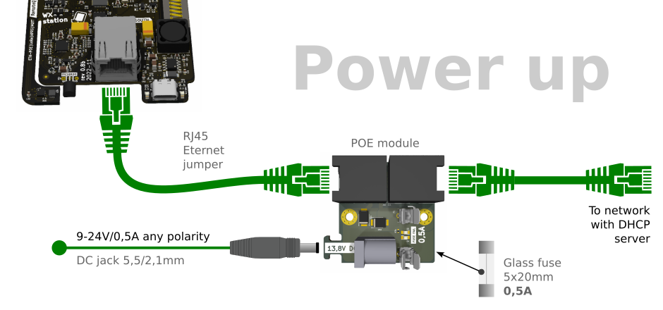
- Connect the weather station to the Ethernet, including the power supply via the POE module, see the picture above
- Connect the weather station with the USB-C cable to the computer
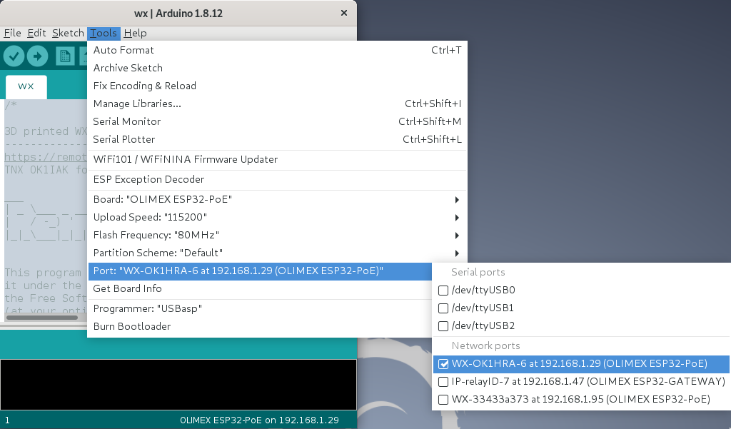
- In the Arduino IDE menu, select Tools/Port: your port
- Select the menu Tools/Serial monitor (or press Ctrl+Shift+M)
- In the bottom sheet of the monitor, choose the speed of 115200 baud and (CR)
- Place the cursor in the upper input line and press Enter
Telnet connect
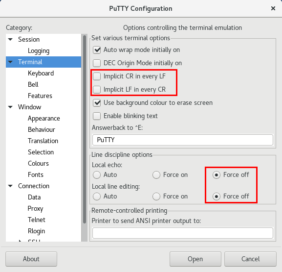
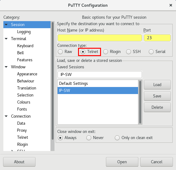
- Download and install PuTTY
-
- select Telnet
- port 23
- write IP address (saved from Reading the access key)
- Sessions may be saved for next time
- for connect press Open
- Login confirm with press
y
- Now answer four times the question of what character is on random selected position, in your key (key saved from Reading the access key). Key formated in groups of ten - FOR EXAMPLE
Position  KEY
 1-10     pP75tf8qrF
11-20     y4SK57dpnC
21-30     fpag8x9eZ4
31-40     IsueSv4jCY
41-50     pX3lpK4UPD
51-60     ij1bbLEQRu
61-70     XRr9dfoJje
71-80     44u5MYQdcm
81-90     B68NpG7F0t
91-100    5mD04pAE6s
- if you enter wrong three times, login will be blocked for next ten minutes (It can be worked around by resetting the power supply to the weather station).
- After login your IP address will be stored in the EEPROM and next key not will be required only if change your IP address
- for Logout press q
Setup
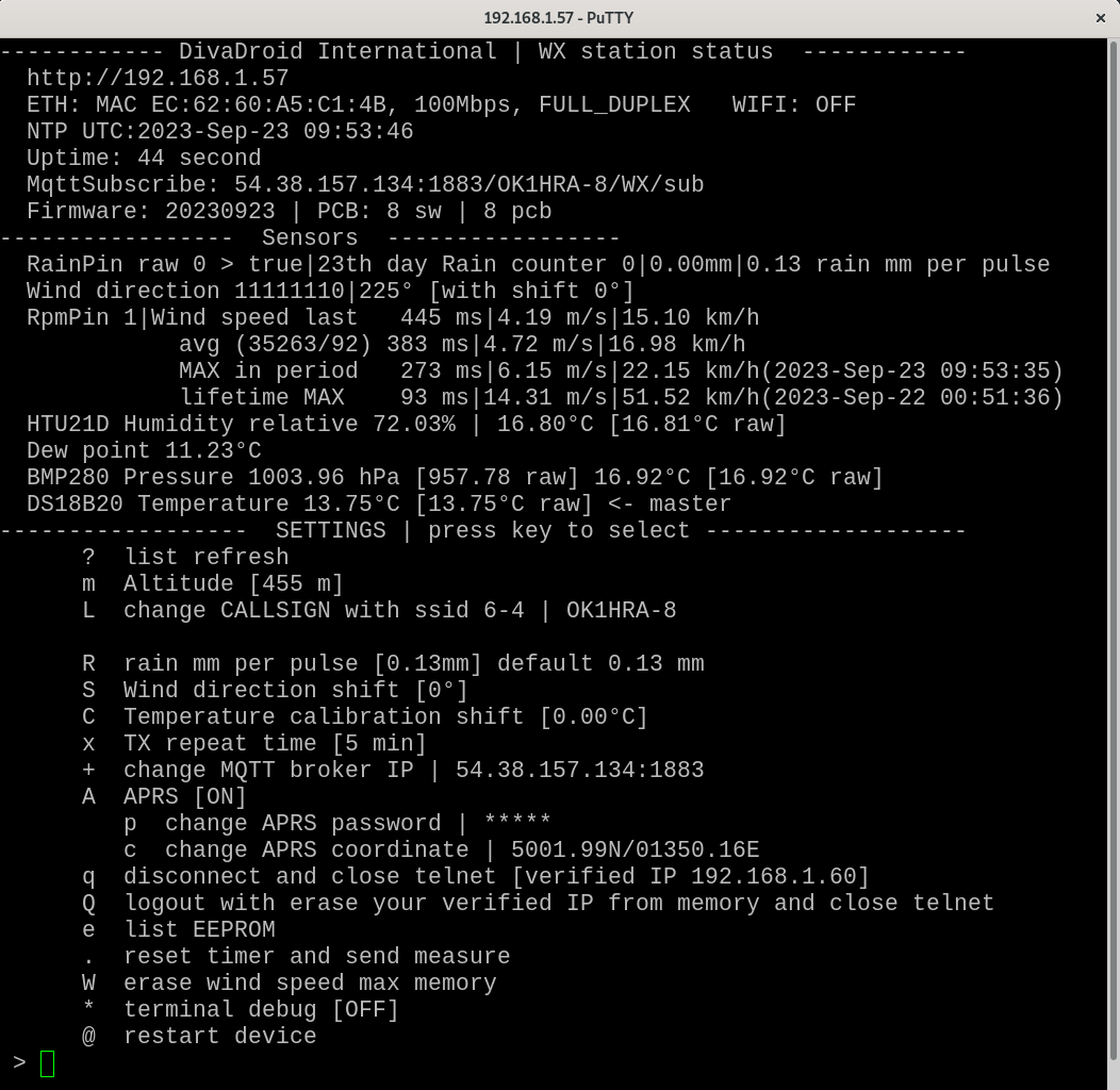
Telnet's CLI (Command Line Interface) consists of three parts:
- WX station status
- Network interface information (IP, MAC address)
- UTC time read from the NTP server (indicates a functional connection to the Internet)
- Uptime
- MQTT borker IP:port/topic
- Firmware and PCB revision
- Sensors (raw and resulting sensor values)
- RainPin - analog status on the input pin and recalculated values
- Wind direction - bit value of parallel converter and output values
- RpMPin - currently read digital input value (1 = without magnet) and length of the last pulse
- + statistics for the last period and the maximum historically measured value with a time stamp
- HTU21D - sensor values (in square brackets with added Temperature calibration shift value)
- Calculated dew point
- BMP280 - sensor values (pressure in square brackets converted to sea level)
- DS18B20 - sensor value
- SETTINGS
Used to set the necessary values. Press the letter from the left column to call up the required menu
WiFi e-ink display connection
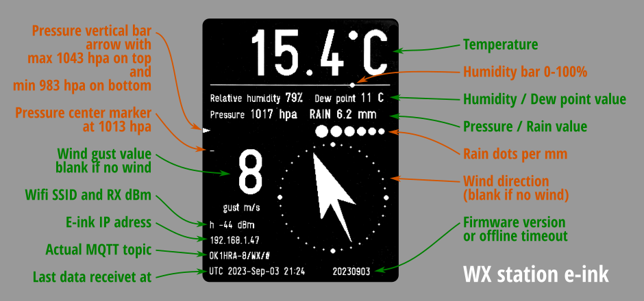
To display the values from the weather station on the WiFi e-ink display, use the tutorial on GitHub
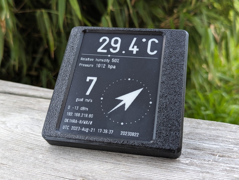
Web interface
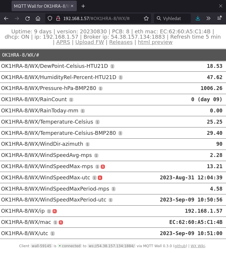
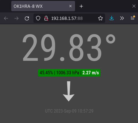
If you enter the IP address of your weather station in the web browser, it will be displayed
- The page header displays basic information and important links
Firmware compilation
- Install Arduino IDE
- Install ESP32 support from GitHub
- prefered via board manager
- Install Arduino libraries
- WiFi, rev 2.0.0
- EEPROM, rev 2.0.0
- Ethernet, rev 2.0.0
- ESPmDNS, rev 2.0.0
- ArduinoOTA, rev 2.0.0
- Update, rev 2.0.0
- AsyncTCP, rev 1.1.1
- ESPAsyncWebServer, rev 1.2.3
- FS, rev 2.0.0
- AsyncElegantOTA, rev 2.2.5
- PubSubClient, rev 2.8
- Wire, rev 2.0.0
- Adafruit_Unified_Senso, rev 1.1.2
- Adafruit_BMP280_Library, rev 2.5.0
- Adafruit_BusIO, rev 1.9.8
- SPI, rev 2.0.0
- Adafruit_HTU21DF_Library, rev 1.0.4
- SD_MMC, rev 2.0.0
- OneWire, rev 2.3.6
- DallasTemperature, rev 3.9.0
- the current list can be found in source code
- Download firmware from GitHub
- Select menu Tools/Board:“OLIMEX ESP32-POE”
- Connect
- USB-C between WX station and PC (Select menu Tools/Port/YOUR-CONNECTED-PORT)
- Upload firmware
- password for OTA upload is remoteqth
Running own services
MQTT broker
MQTT is a universal protocol that is used to communicate the WX station with other devices (WiFi e-ink display). The control node transmitting this information is the MQTT broker. The default settings of the WX station use the public MQTT broker of the Internet at the address remoteqth.com. In order to avoid dependence on an Internet connection or the availability of a public MQTT broker, we recommend that you install your own MQTT broker on a Raspberry PI or other device in the local network. For this you can use some of the public instructions like this one (without installing NodeRed).
After installation, change the settings of two items (MQTT broker IP and MQTT broker port) in the Setup section, according to the IP address of your local MQTT broker.

