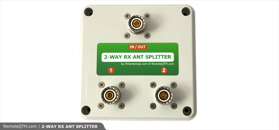
2-way RX splitter / combiner by OK2ZAW
The splitter or combiner is a very useful device. It can provide equal voltages, equal current, or equal power to matched or unmatched loads.
Like all passive splitters and combiners, this device is less than ideal. Isolation is maximum only when at least one port are properly terminated.
In this case isolation between the two splitted/combinated ports is maximum when the main port is properly terminated.
This HW is designed only for RX line. There are some more high current and voltage protections on all ports. Both impedances 50 or 75 Ohm can be selected by the jumper.
Main functions:
- Info:
Broadband: 0.1 MHz to 60 MHz Splitter or Combiner Low loss Protections- high voltage / current 50/75 ohm impedance - easy jumper switch
- Electrostatic protection with glim lamps.
- High power protection.
- Stainless screws.
- Quality PTFE SO-239 connector or N or F connector on request.
- IP56 box.
- Size 10x10 cm (feeder).
- Available as
- KIT : all parts + PCB + box
- Assembled : ready to use
- Assembled : ready to use, with 3 x SO-239 to F adapters
Parameters:
- Info:
- Impedance 50 or 75 Ohm
- Insert loss: around 0,5 dB
- Split 3 dB, together with IL around 3,5 dB
- Isolation more than 30 dB, 160-40 m more than 40 dB
- SWR on splitted ports better than 1:1,1 on HF, resp. 1:1,19 on 6 m
- SWR on main port around 1:1,2 on HF, resp. 1:1,3 on 6 m
- Maximal current continue 100 mA
- Maximal voltage around 65 V
Use:
Antennas splitter RX signal divider One antenna, two RX
Versions:
KIT or assembled Connectors: SO-239, N or with adapters also F
The measured values
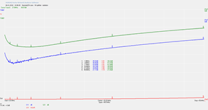
 Isolation and SWR on splitted ports  |
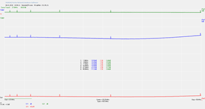
 SWR on main port and Insert loss  |

Download
| 2-way splitter | ||
|---|---|---|
| Schematic and board pic | sch  |
brd  |
| Source files | KiCAD283 | |

|
||
|
We believe open source is a better way of doing things. View and download the Shield Schematic and PCB files. The hardware designs are released under the Attribution-NonCommercial 2.0 Generic |
||


