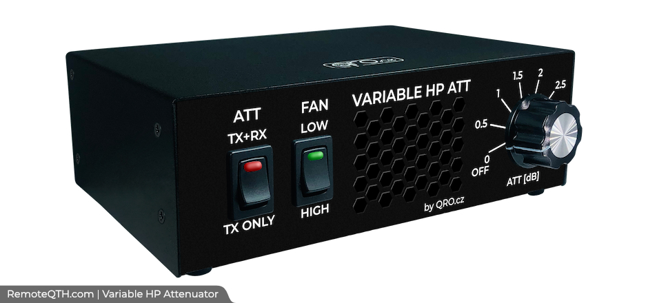
Variable high power ATTENUATOR (ATT) by OK2ZAW
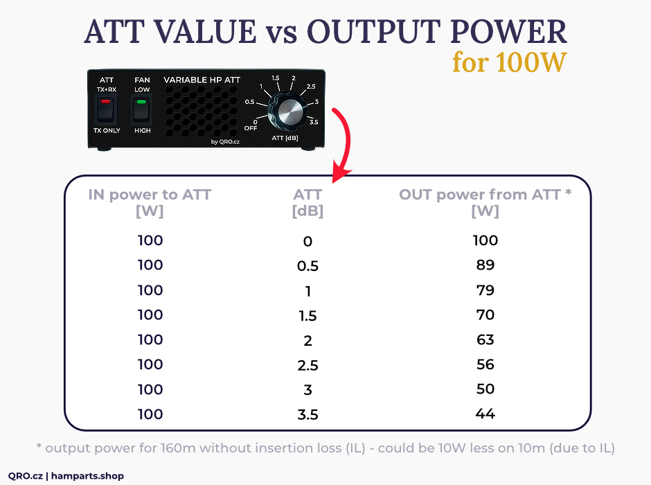
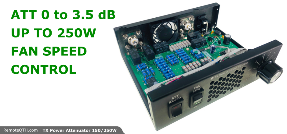
Attenuator is a passive device but can be very helpful for measuring tools, power aplifiers and multibeaming with more power amplifiers with different gain or input power level. There are two fan speeds including automatic speed increase by the PCB temperature. You can use ATT only during TX - controlled by PTT or in RX and TX.
Main functions:
Frequency range DC to 30 MHz High power variable ATT 250W CW / SSB (PEP) 150W RTTY (PEP) 150W CW / SSB (contest mode) 100W RTTY (contest mode)
ATT works in two modes: ATT in RX and TX way ATT only in TX way - controlled by PTT
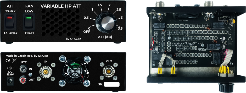
- Internal FAN
- Two fan speeds
- Automatic speed control
- Lower noise compare to old version
- PTT IN/OUT works in sniffer mode!
- Quality PTFE SO-239 connector.
Parameters:
- Supply voltage 12 - 15 V DC, max. 1 A
- Input power CW/SSB and RTTY: 250 W / 150 W PEP in DX mode & 150 W / 100 W in contest mode
- Fan speed control
- Frequency range DC to 30 MHz
- Worst SWR (30 MHz) 1:1,2
- Maximal sloping 1 to 30 MHz: 0,5 dB
Application:
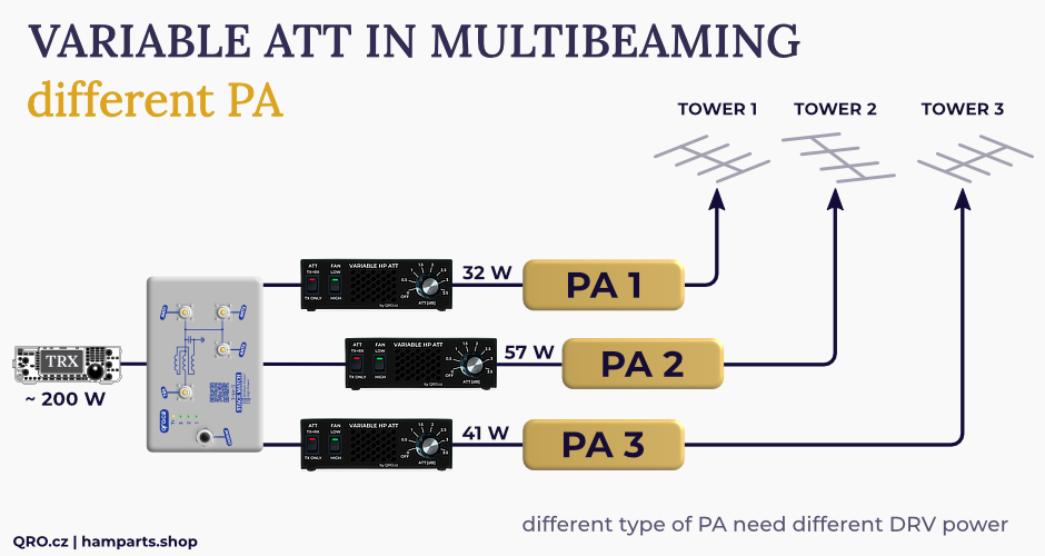
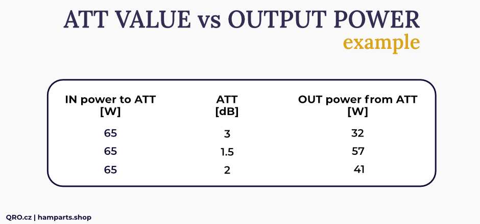
PA building - changing DRV power PA input ATT More PA - different driver power
Measured values - SMD version
 ATT BYPASS 0dB  |
 ATT 0.5dB  |
 ATT 1dB  |
 ATT 1.5dB  |
 ATT 2dB  |
 ATT 2.5dB  |
 ATT 3dB  |
 ATT 3.5dB  |
Measured values - OLD THT version
 ATT BYPASS 0dB  |
 ATT 0.5dB  |
 ATT 1dB  |
 ATT 1.5dB  |
 ATT 2dB  |
 ATT 2.5dB  |
 ATT 3dB  |
 ATT 3.5dB  |
 ATT the best SWR  |
 ATT worst SWR  |
Example for the Multibeaming:
Download
| Source codes | ||
|---|---|---|
| ATT SMD ver. 2.3 (2022) | schematic  |
board  |
| ATT older THT version | sch  |
brd  |
| Source files | eagle342 | |

|
||
|
We believe open source is a better way of doing things. View and download the Shield Schematic and PCB Kicad/Eagle CAD files, LibreCAD .DXF, or Inkscape .SVG files. The hardware designs are released under the Attribution-NonCommercial 2.0 Generic |
||
Users implementation
Really nice HS of S52AW!  |
Really nice HS of S52AW!  |
80m full size Y at S52AW  |


