


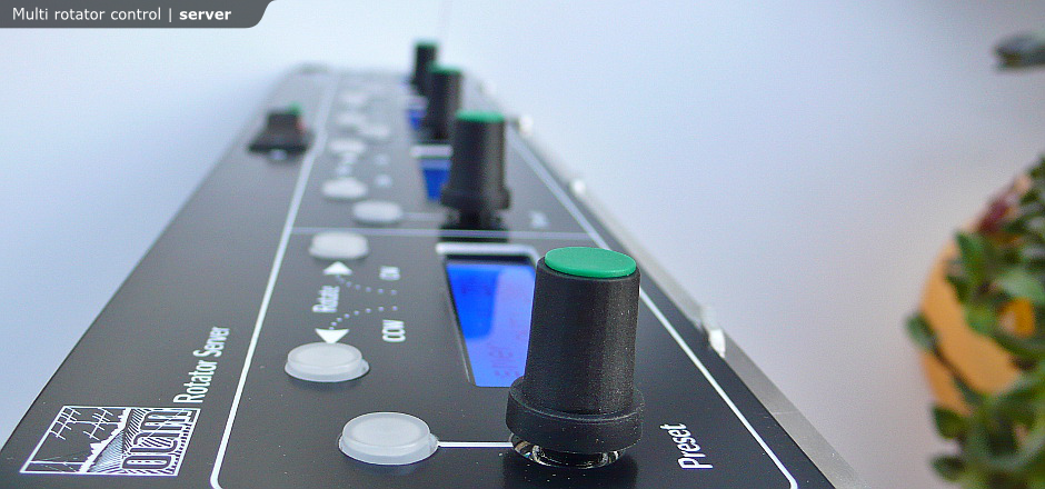
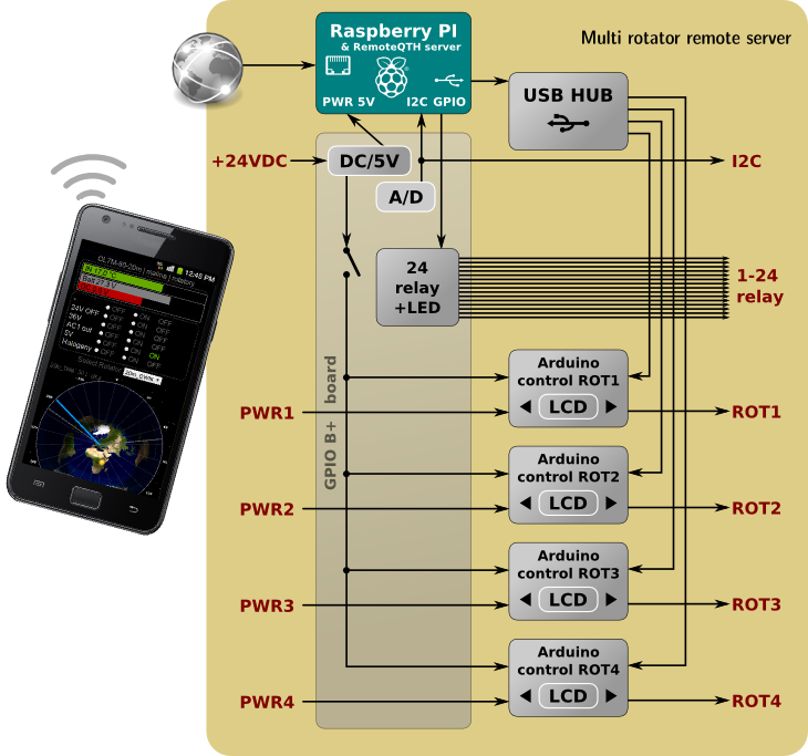
Web control four rotator, fifteen relays and many other features that come from Raspberry PI RemoteQTH server.
Developed for contest station "Policko" OL7M


Main functions:
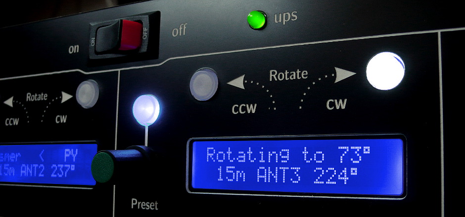
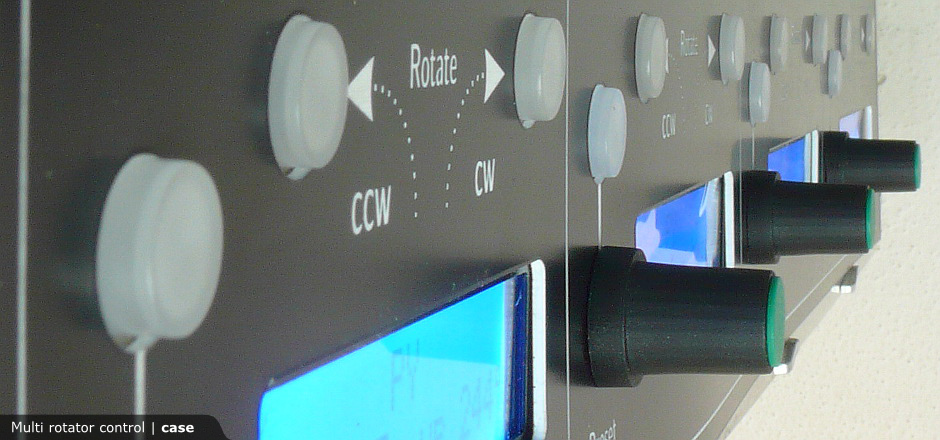
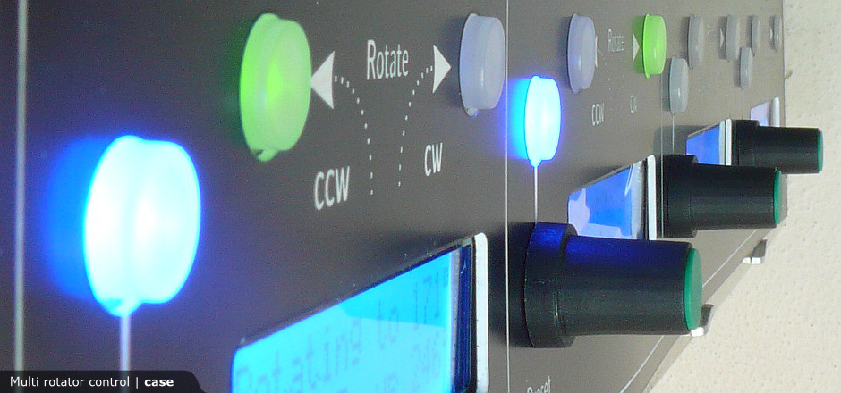
- Control the four rotators using the light buttons,
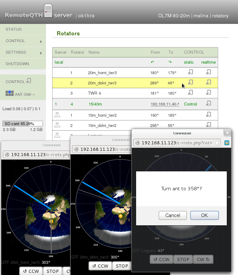
rotary encoder and with a two-line display for each rotor. - Same control remoted via web interface or telnet
- only click to map and confirm rotating.
- Rotator module can directly control the motor of the rotator
- DC version of the phase-change
- AC version switching CW or CCW winding
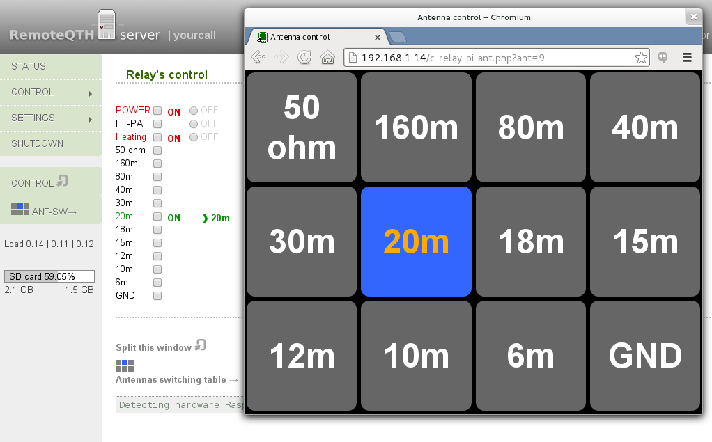
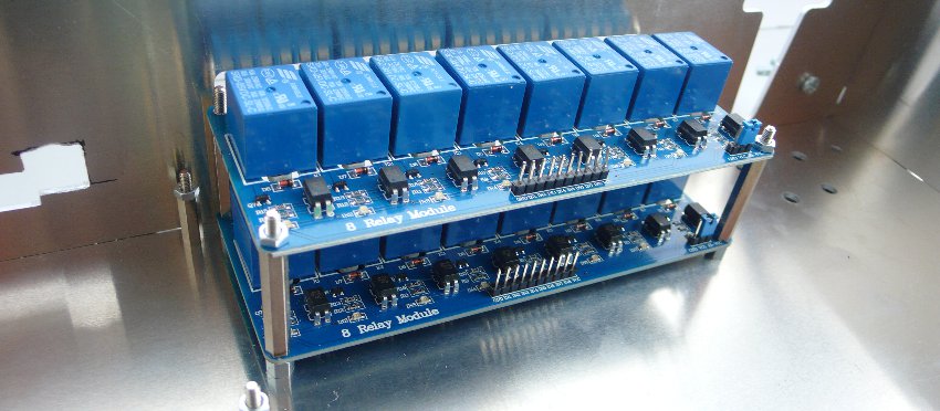
- 24 freely configurable relay (15 in model B) (first used for server power on/off)
as single pole, single throw or single pole, more throw
- suitable for switching antennas. - GPIO interface power board associating functions
- Relay switching from GPIO
- DC/DC converters power supply 5V for Raspberry PI
- DC/DC converters power supply 5V for four arduino rotators module.
Turns ON the first GPIO output. - Available four DC/DC converters - custom voltage power supply for each motor of rotator. In the range of 2 to 37V an max current 3A.
- Include A/D converter for four voltage measurement
- Expand I2C bus - available connect next temperature or voltage sensors
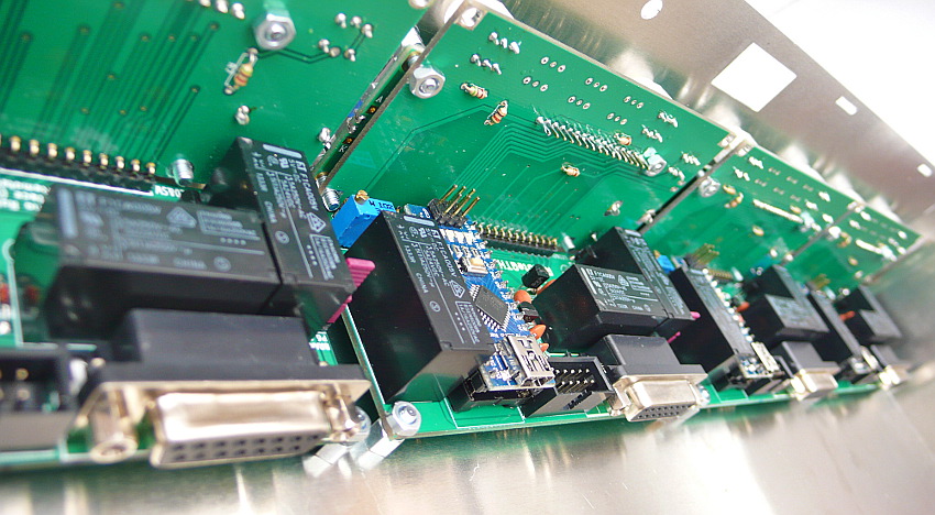
- All in simple 2U Rack case.
- Case made to measure from 2 mm aluminium.
- Laser engraving plastic front panel.
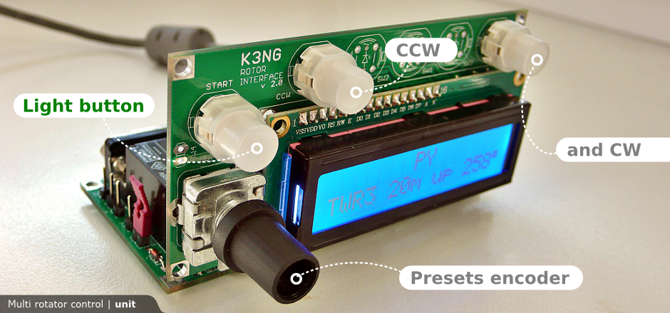
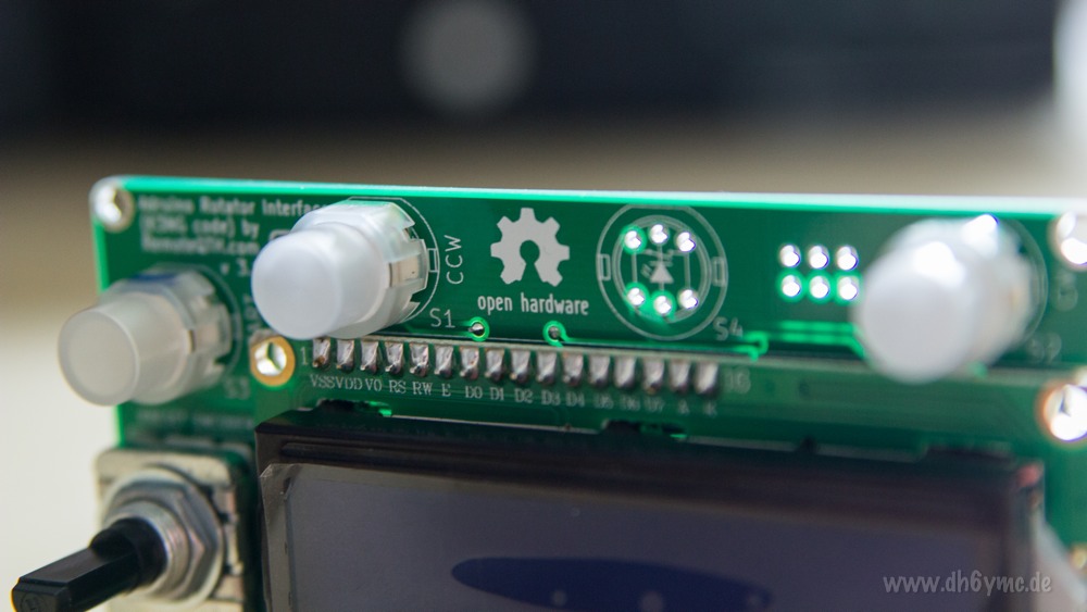
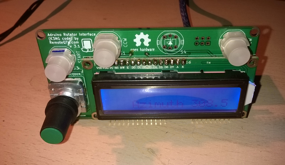
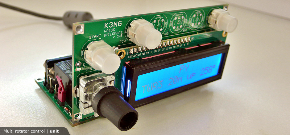
- Each the rotator unit interface, based on arduino (code by K3NG) contains:
- LCD.
- Lighting button (CW, CCW, Start).
- Preset encoder.
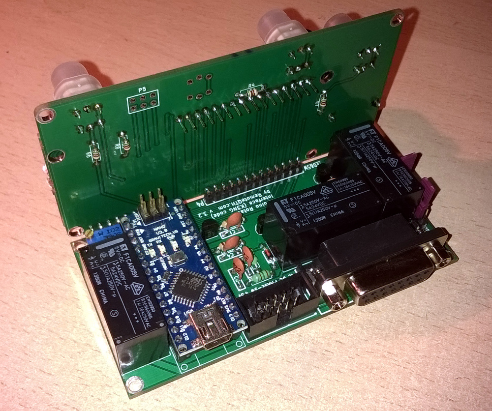
- Three relay (CW, CCW and Brake).
- Arduino nano module.
- Ready for AC and DC rotators.
- Analog input.
- 5V power voltage.
- Server requires a DC power supply ranging from 9 to 40 volts.
Voltage is dependent to the rotator, if we are powered motor directly from the server. - If you have a rotator AC motor, the server has terminals
for connecting the AC voltage for each rotor separately. - Another server utilization
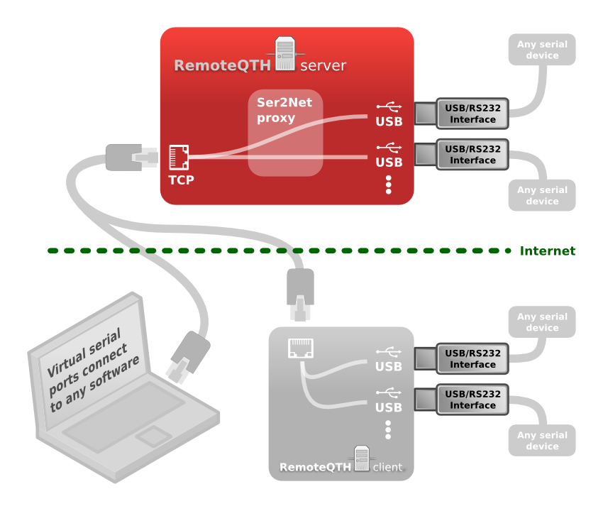
- Export USB/serial interface to IP.
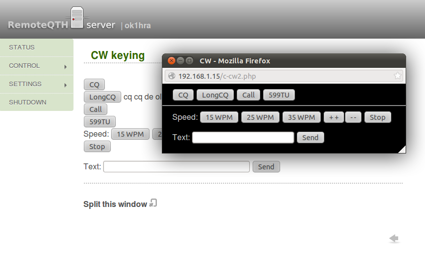
- CW keying from web interface.
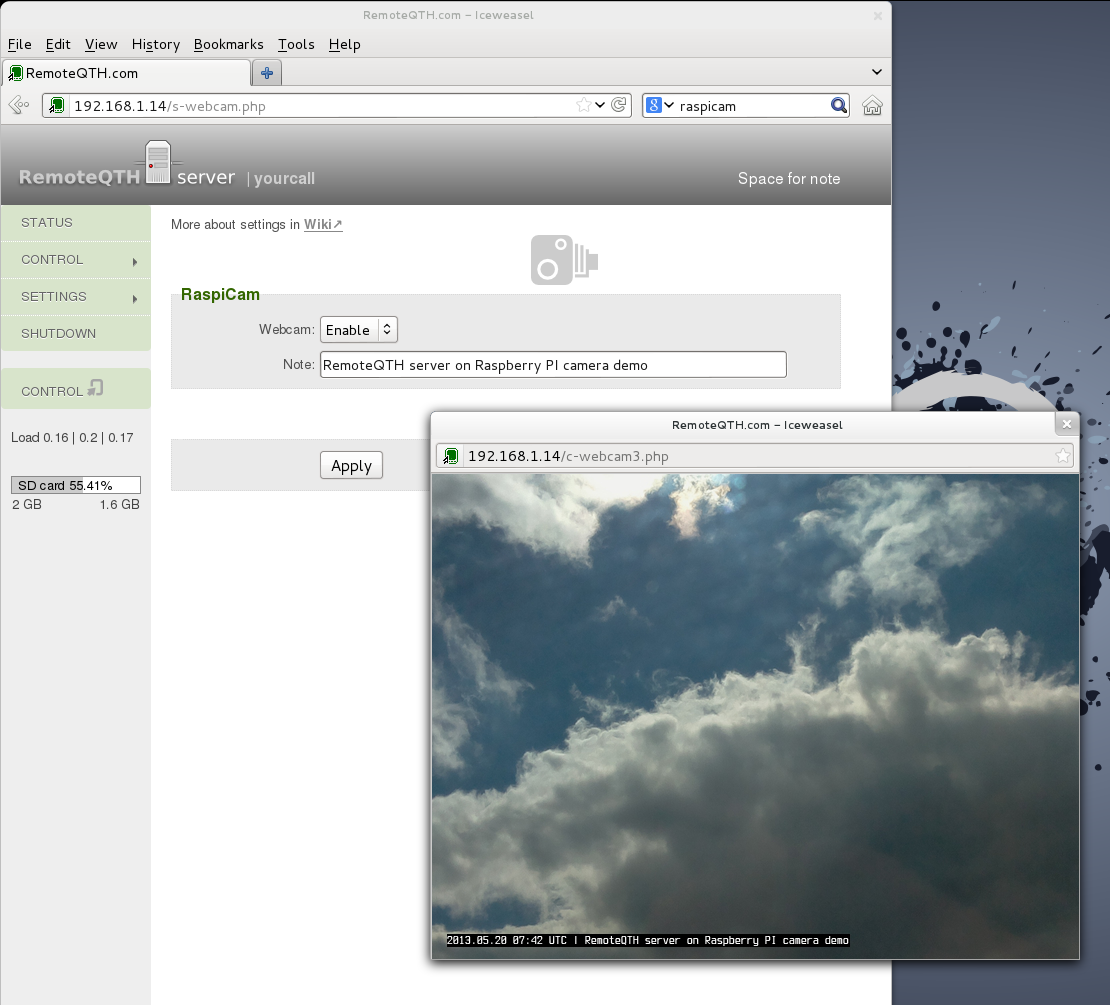
- Connection RaspiCam Webcam.
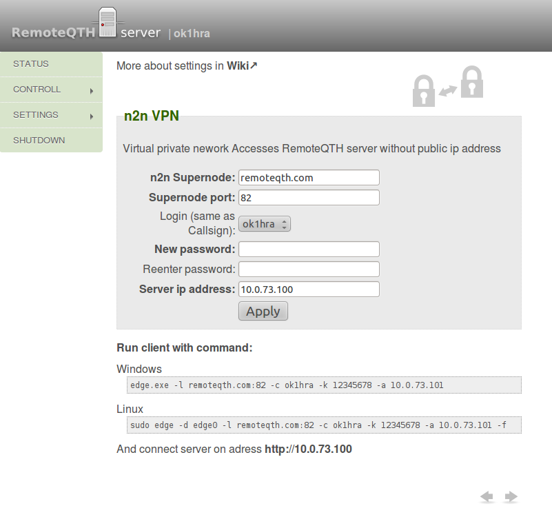
- Access without public IP adress (n2n vpn).
- Switching relay by TRX frequency using Band decoder function.
- Export USB/serial interface to IP.
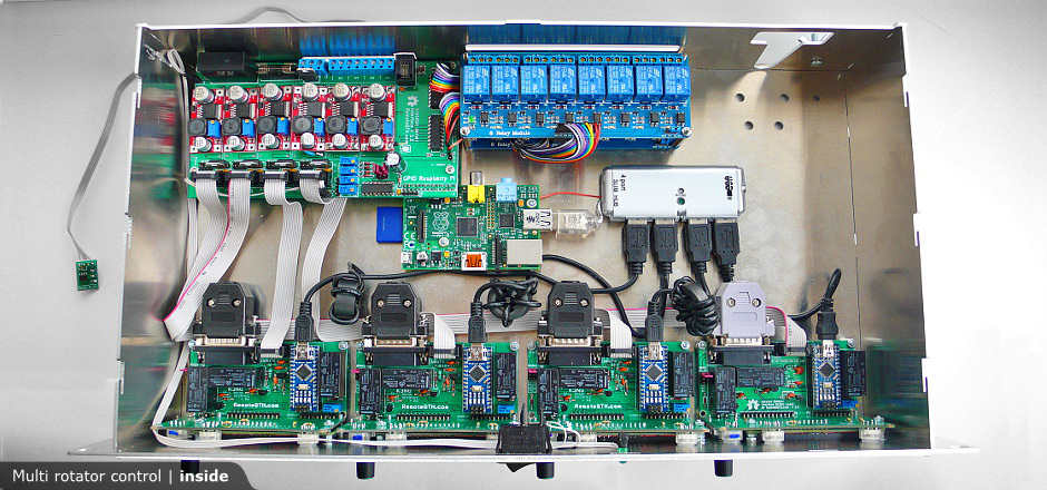
- Necessary components
- Rack case.
- Rapsberry PI + 4GB SD card with RemoteQTH server.
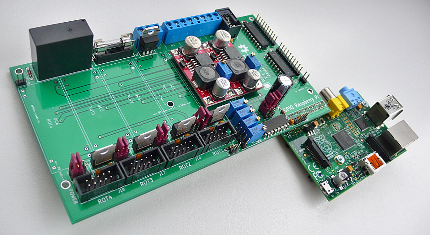
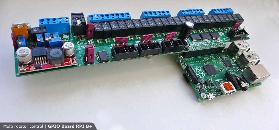
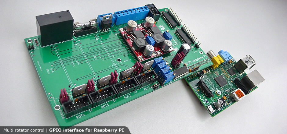
- GPIO interface power board.
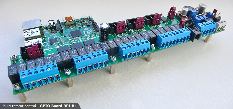
- Relay board.
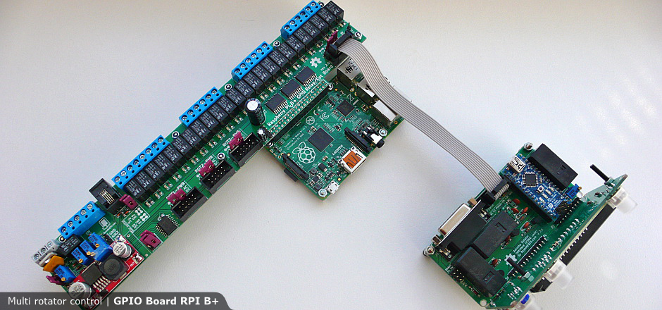
- Four arduino rotator interface.
- Usb hub with external power supply.
- DC power supply 9-40V dependency to max DC rotator voltage.
- AC power supply if AC rotator instaled.
 Block diagram (model B+) |
 GPIO Board circuit (model 2/B+) |
 Rotator control circuit |
 Block diagram (model B) |
 GPIO Board circuit (model B) |
Unit test:
Download
| Rotator module PCB | |||||
|---|---|---|---|---|---|
| v3.3 | sch  |
front.brd  |
back.brd  |
kicad3184 | |
| v3.2 | sch |
front.brd  |
back.brd  |
kicad1048 | |
| v3.1 | sch  |
front.brd  |
back.brd  |
kicad1063 | |
| v2 lcd | pcb 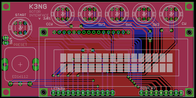 |
sch 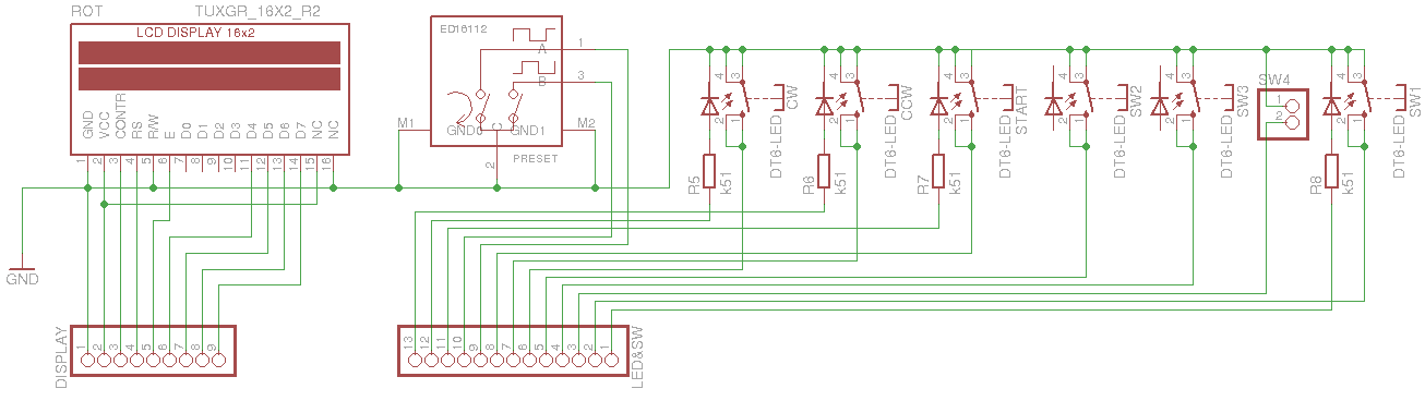 |
eagle1077 | ||
| v2 base | pcb 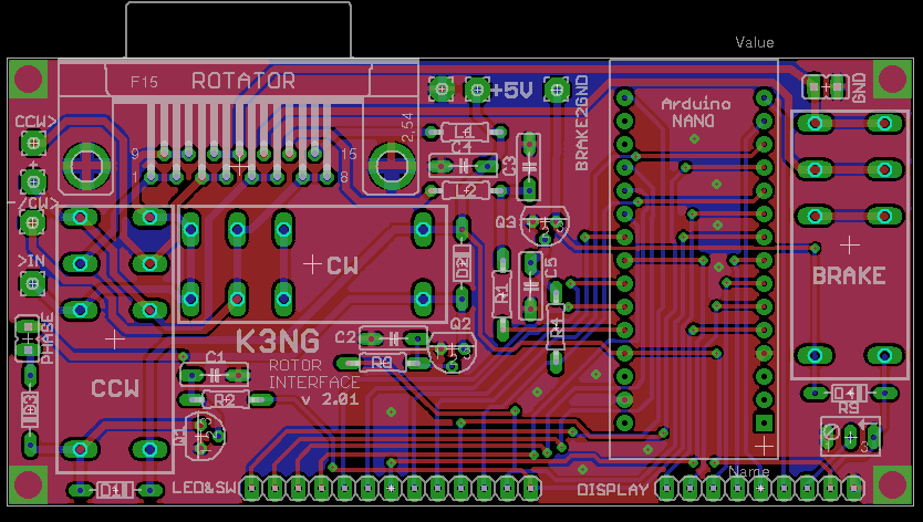 |
sch 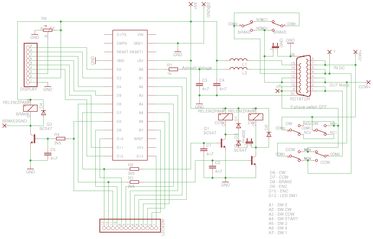 |
eagle1012 | ||
| Arduino firmware | |||||
| by K3NG | stable | unstable | doc | pins.h1729 | |
| Raspberry PI GPIO interface PCB | |||||
| Model RPI2/B+ v2.2 | sch |
brd 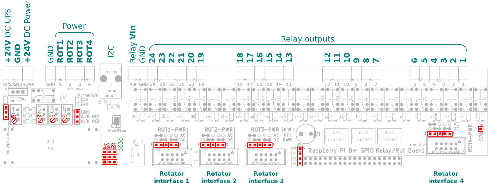 |
kicad900 | wiki | |
| Model B+ v2.1 | sch  |
brd 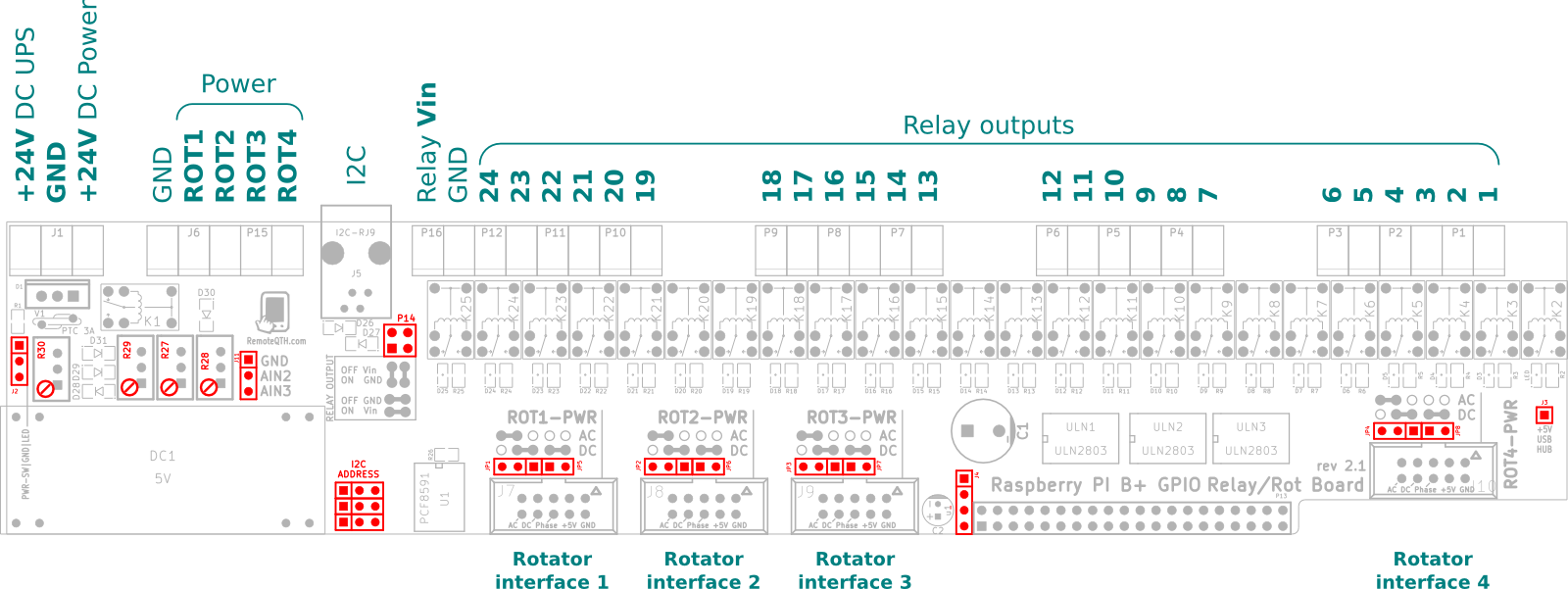 |
kicad895 | ||
| Model B v1.2 | sch |
brd  |
kicad841 | ||
| I2C temperature sensor PCB | |||||
| v1.0 | sch  |
front.brd  |
kicad878 | ||
| 2U rack case (19-inch x 2u (3.5") x 9.5") | |||||
| Version 6 | full.DXF902 | DXF4cutter938 | |||
| Version 4 | full.DXF1028 | DXF4cutter1025 | wiki | ||
| Front panel design (inkscape) | svg  |
||||
 Open-Hardware Open-Hardware
|

|
||||
|
We believe open source is a better way of doing things. View and download the Shield Schematic and PCB Kicad/Eagle CAD files, LibreCAD .DXF, or Inkscape .SVG files. The hardware designs are released under the Creative Commons Attribution-ShareAlike 4.0 International License |
|||||
Users implementation
 DH6YMC |
 F4EGA |
 F4EGA |


