


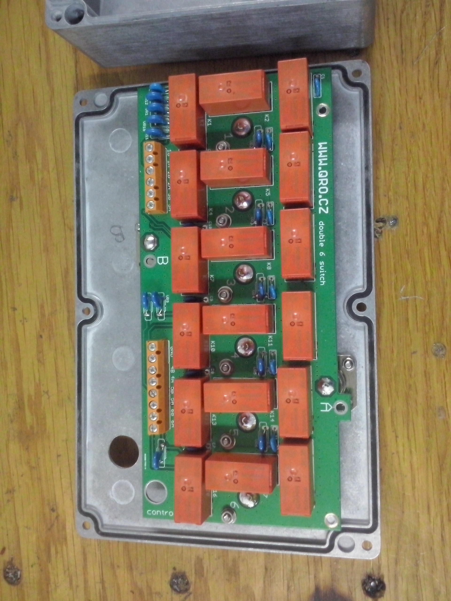
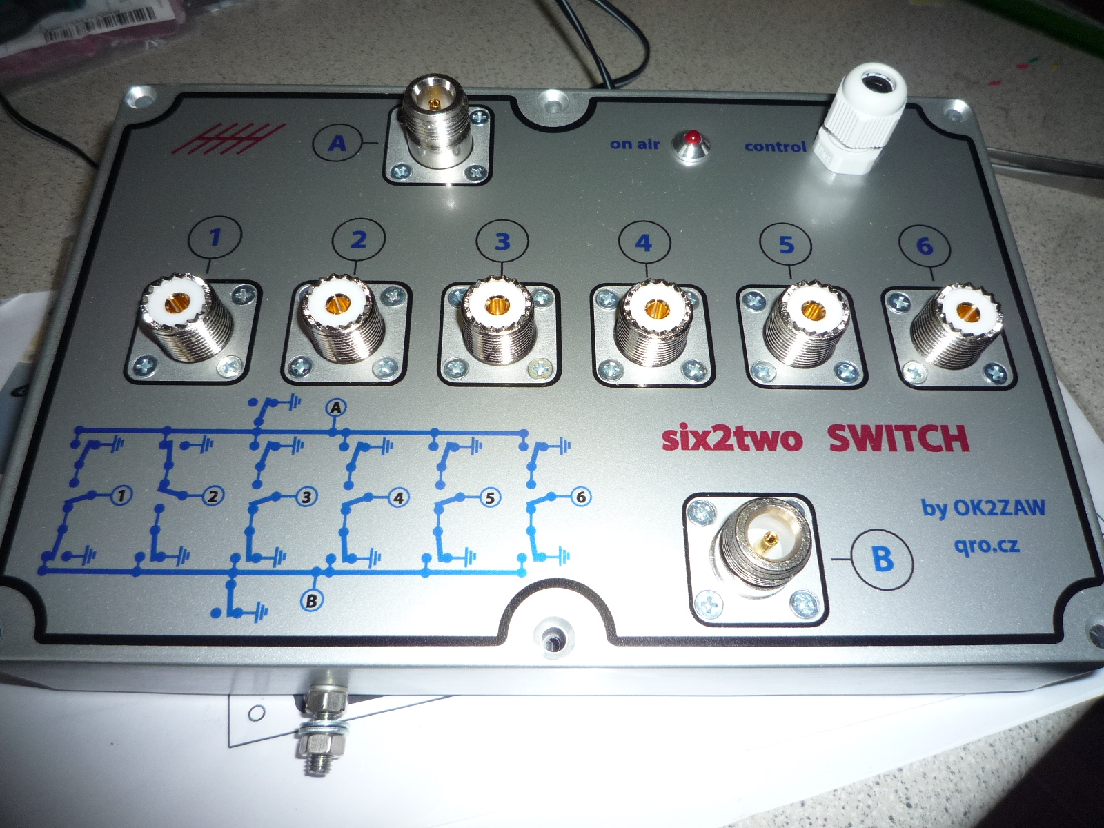
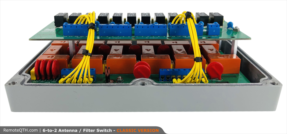
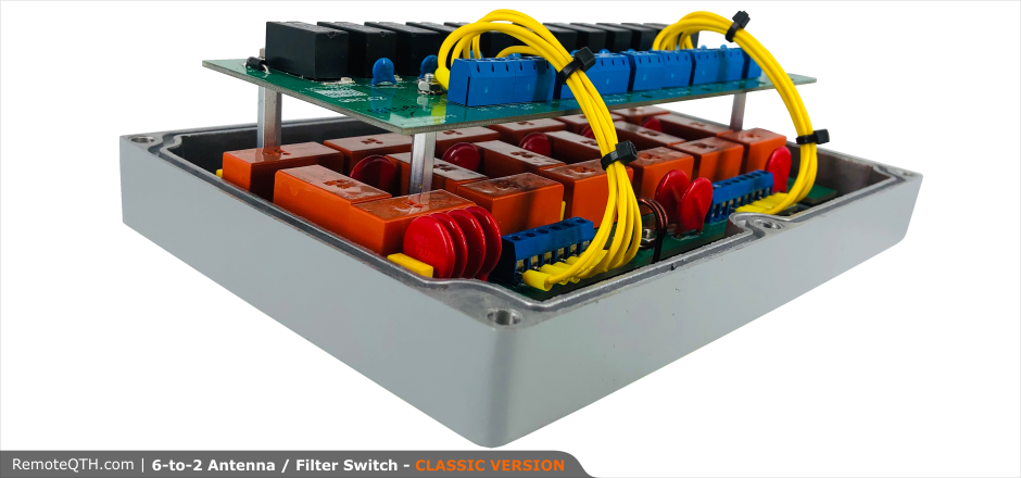
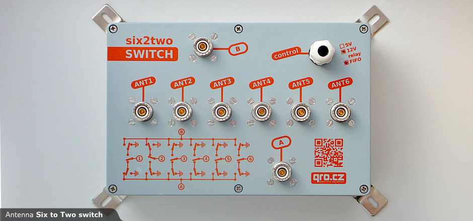
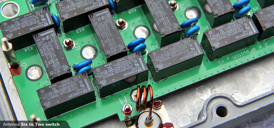
Antenna six to two (SIX2TWO) switch by OK2ZAW
Can be controlled by:


Main functions:
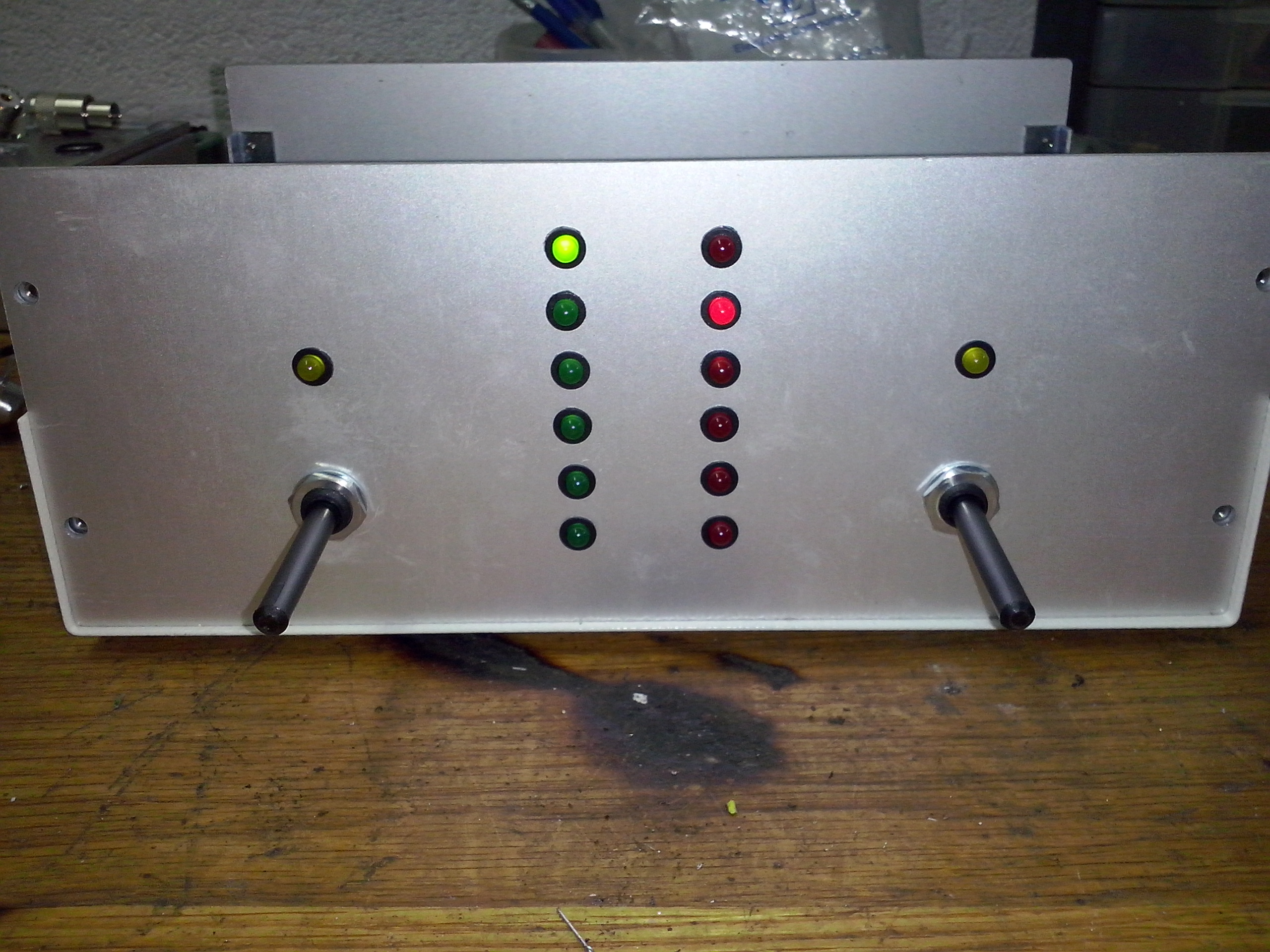
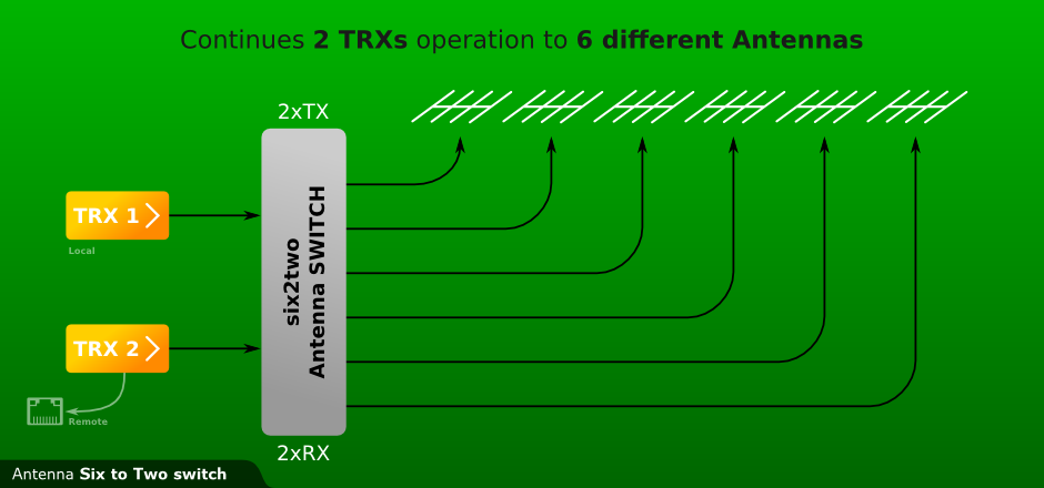
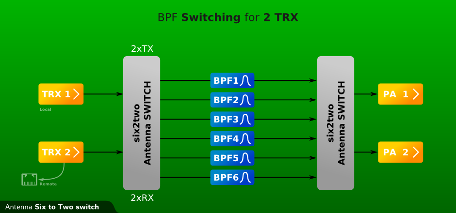
- Six outputs to two inputs.
- Frequency range DC-30 MHz
- Characteristic impedance 50 ohm
- High isolation between A nd B ports, better than 80dB.
- Insertion loss better than 0.05dB.
- Power rating DC to 30 MHz
- 2 kW continue wave
- 3,5 kW PEP (SWR < 1:1.7) (tested with OM-3500)
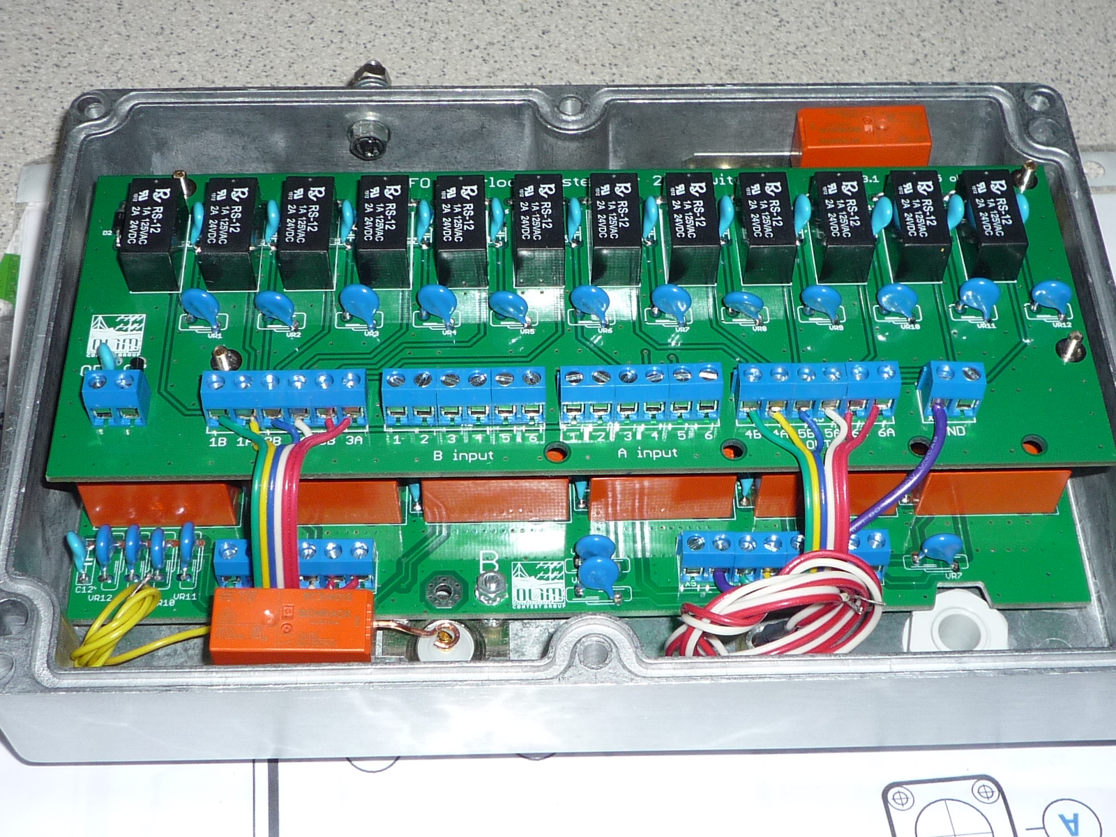
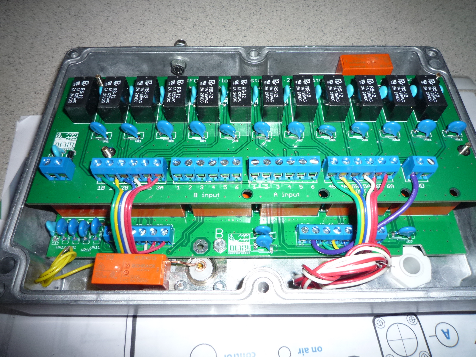
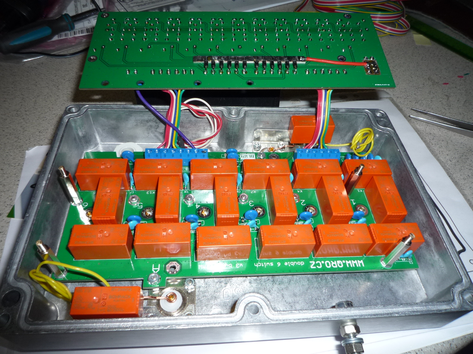
- High quality PCB thickness 2 mm
- Two relay version, 12 or 5 Volt
- Connectors PL-259 female with gold plated.
- Power consumption < 4W.
- Unselected antenna ports are grounded.Do you need 50 Ohm loads for Triplexer?
- Without DC power the antenna ports are grounded.Triplexer version
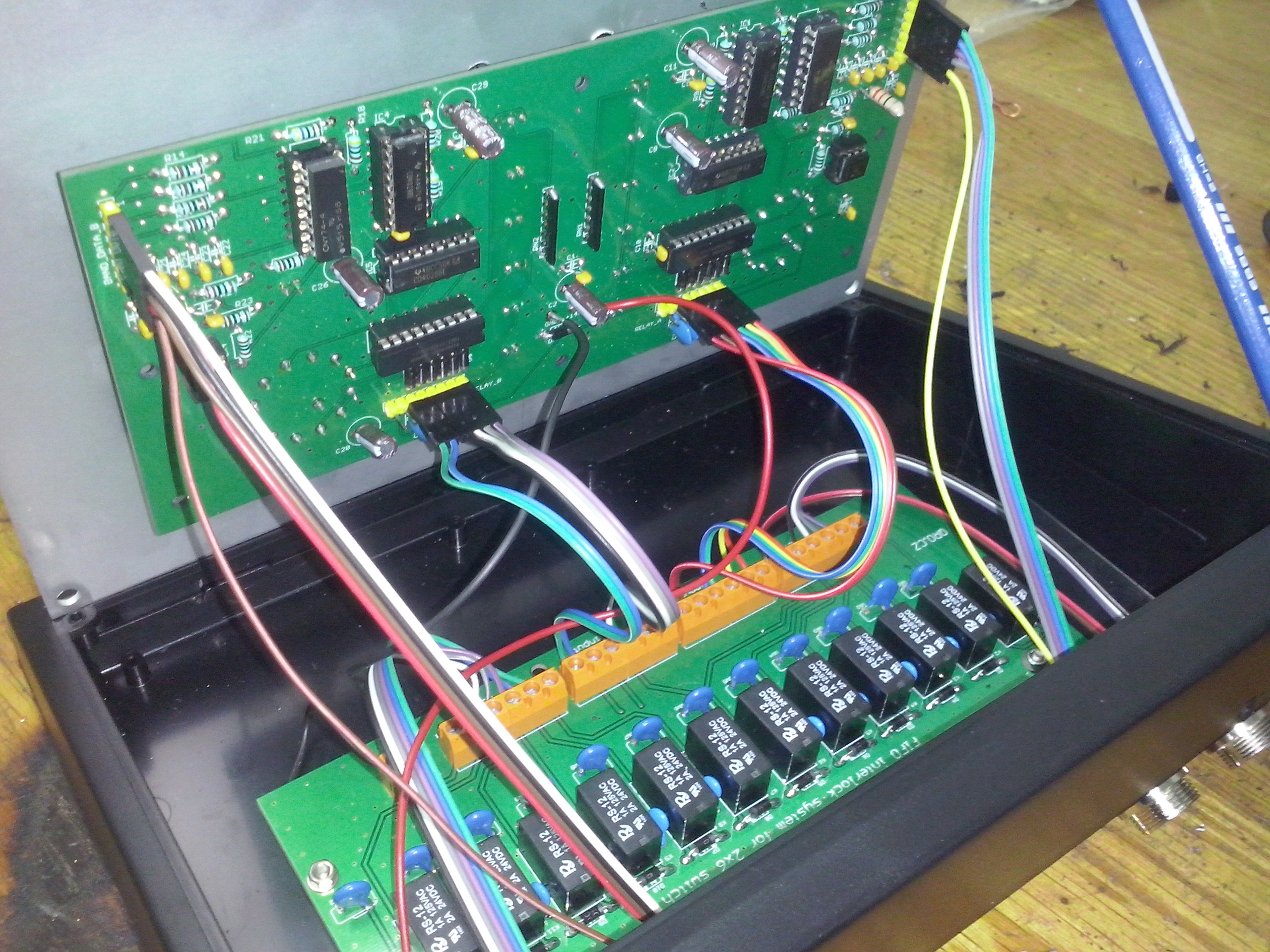
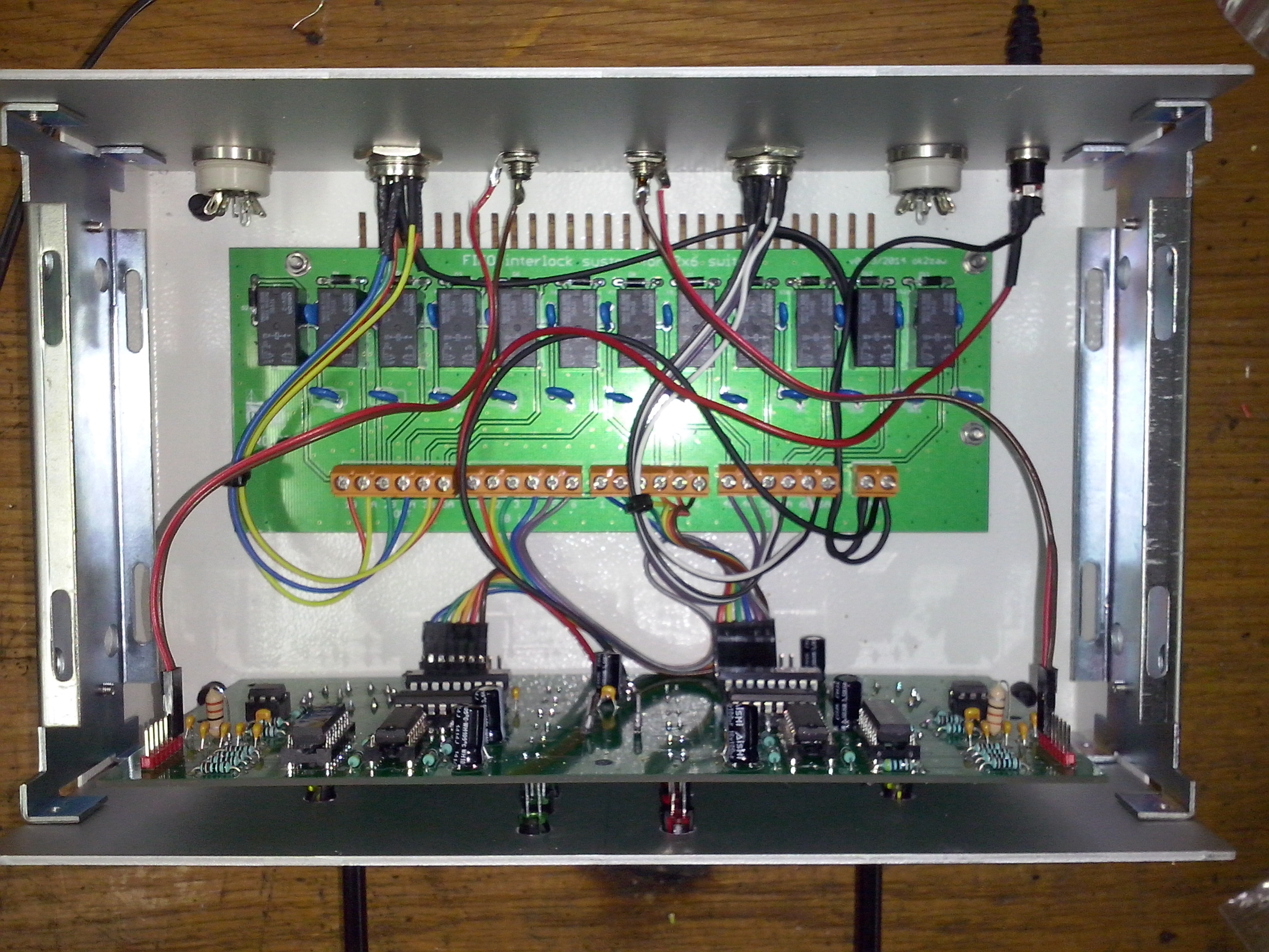
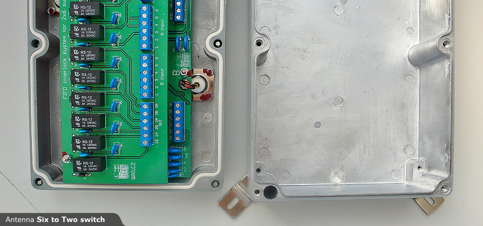
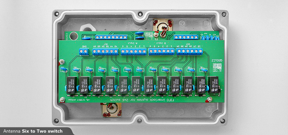
- Hazardous states are excluded with FIFO interlock additional board.
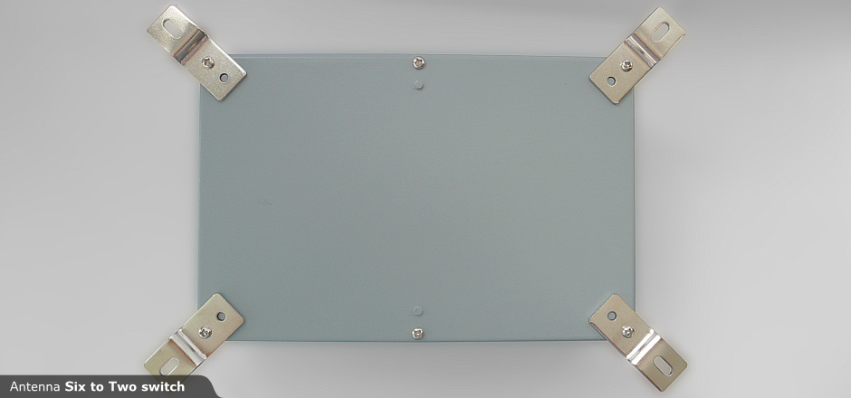
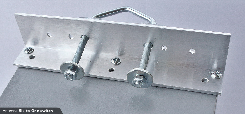
- Aluminium shield enclosure.
- Aluminium mounting holder with bracket (pipe max 52mm). More info
- Size 222 x 145 x 75 mm
- Weight 2 kg
Isolation example:
- TRX A output power 1kW = 60dBm
- isolation to port B is 80dB -> 60dBm - 80dB = -20dBm
- ~ 10uW at TRX port B
Do NOT forget to:
- Your antennas isolation!
- The safe power isolation is not only about the switch isolation!
- Never switch relay during TX!
The measured values
 VSWR |
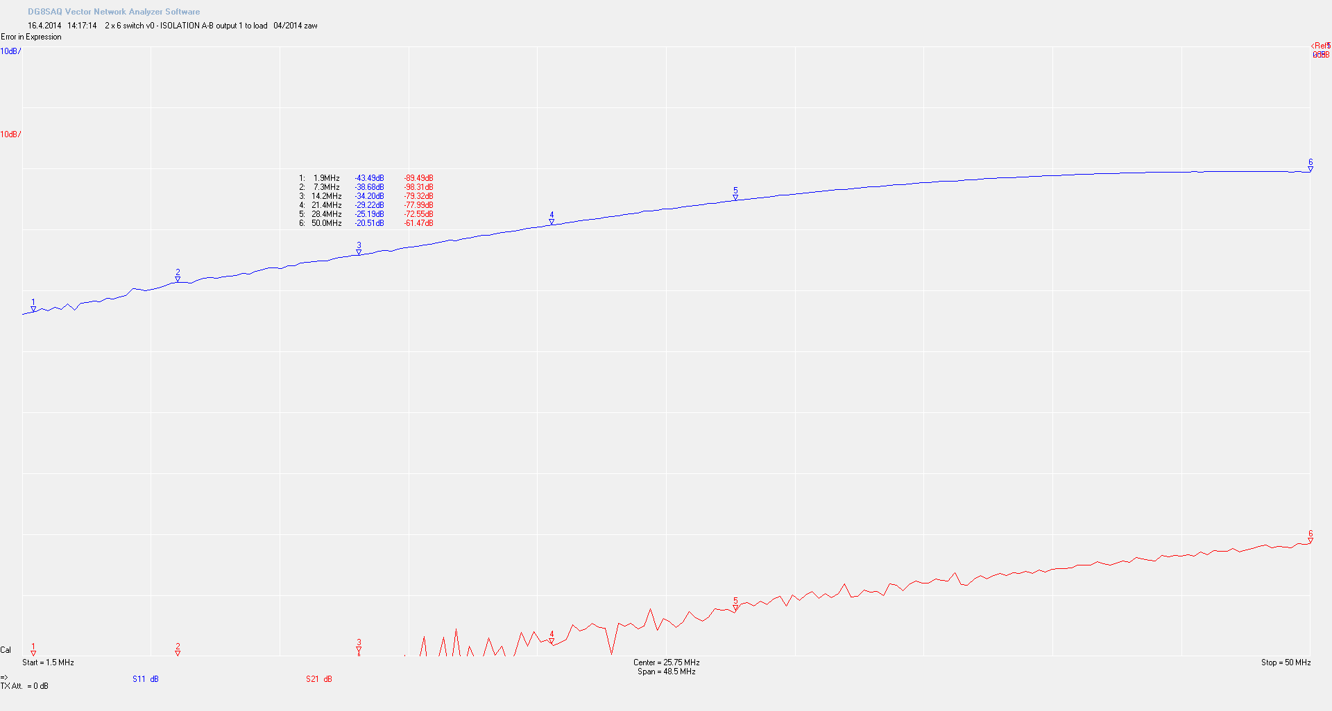
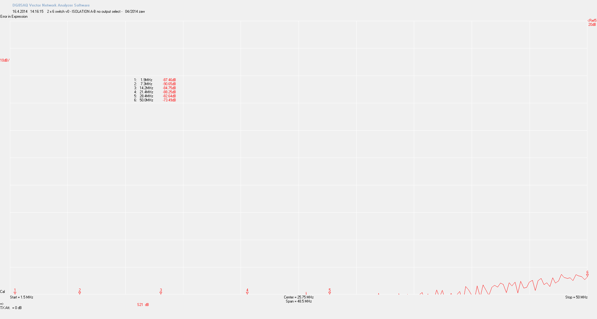 Isolation A-B |
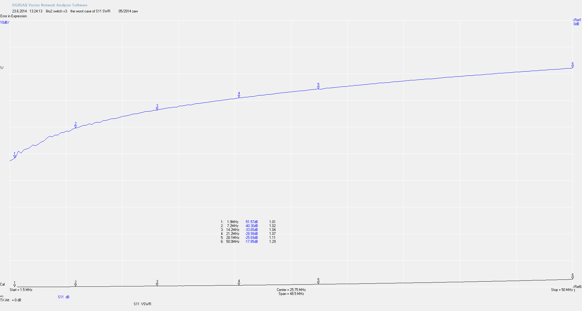 The worst SWR |
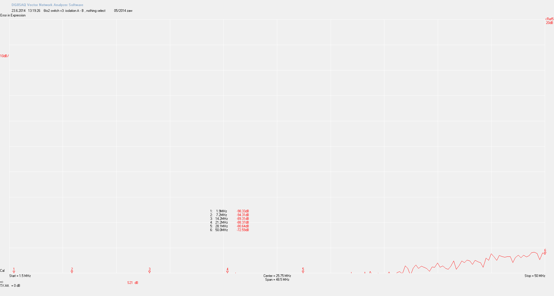 Isolation A to B |
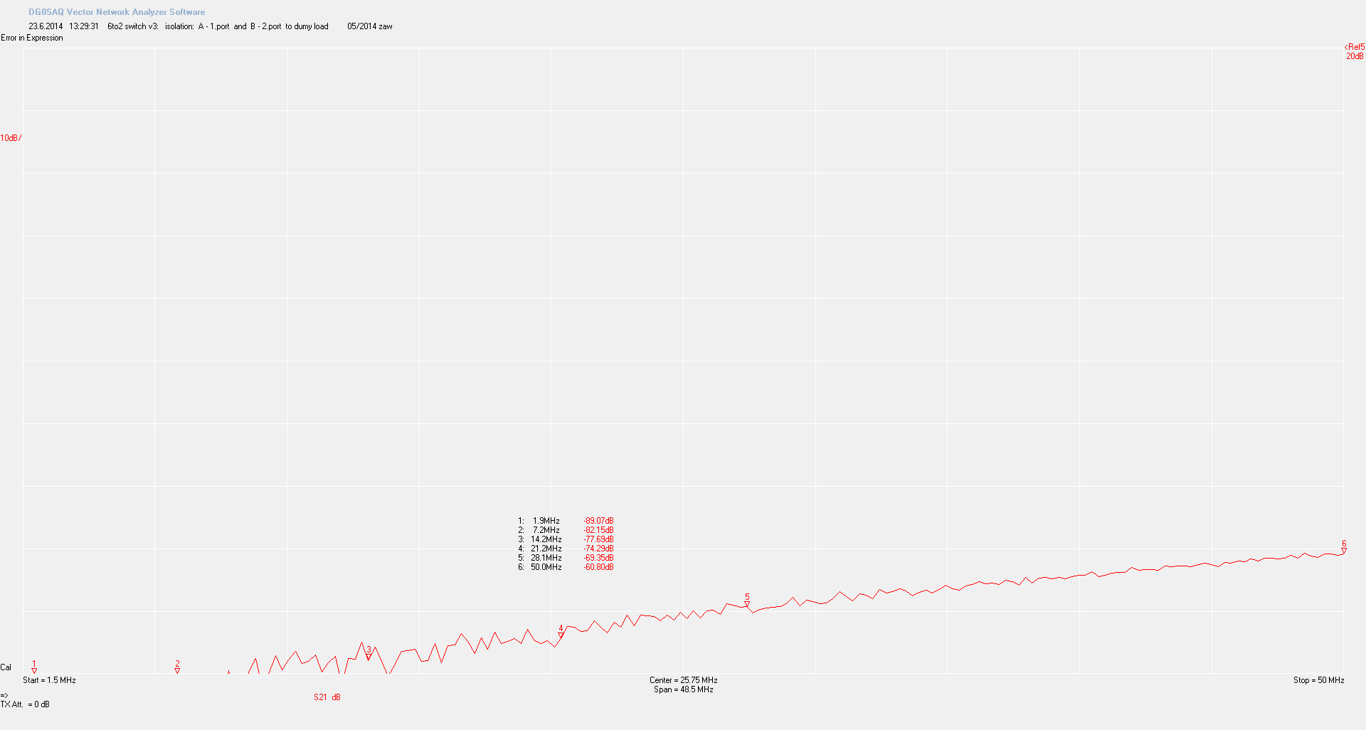 Isolation port A to 1, B to 2 |
 Insert loss port B to 6 |
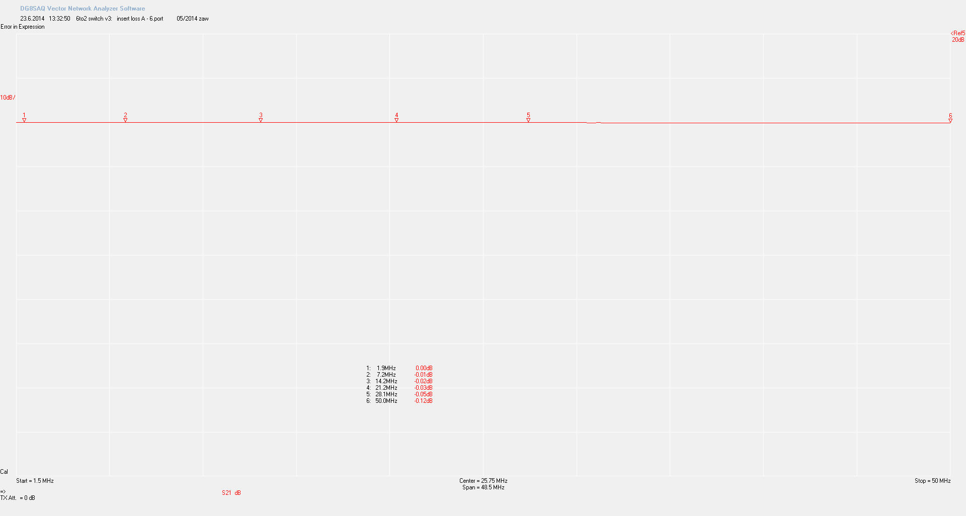 Insert loss port A to 6 |
Download
| 6 to 2 Antenna switch | |||||
|---|---|---|---|---|---|
| main version 3 | pcb 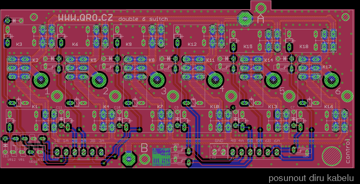 |
sch 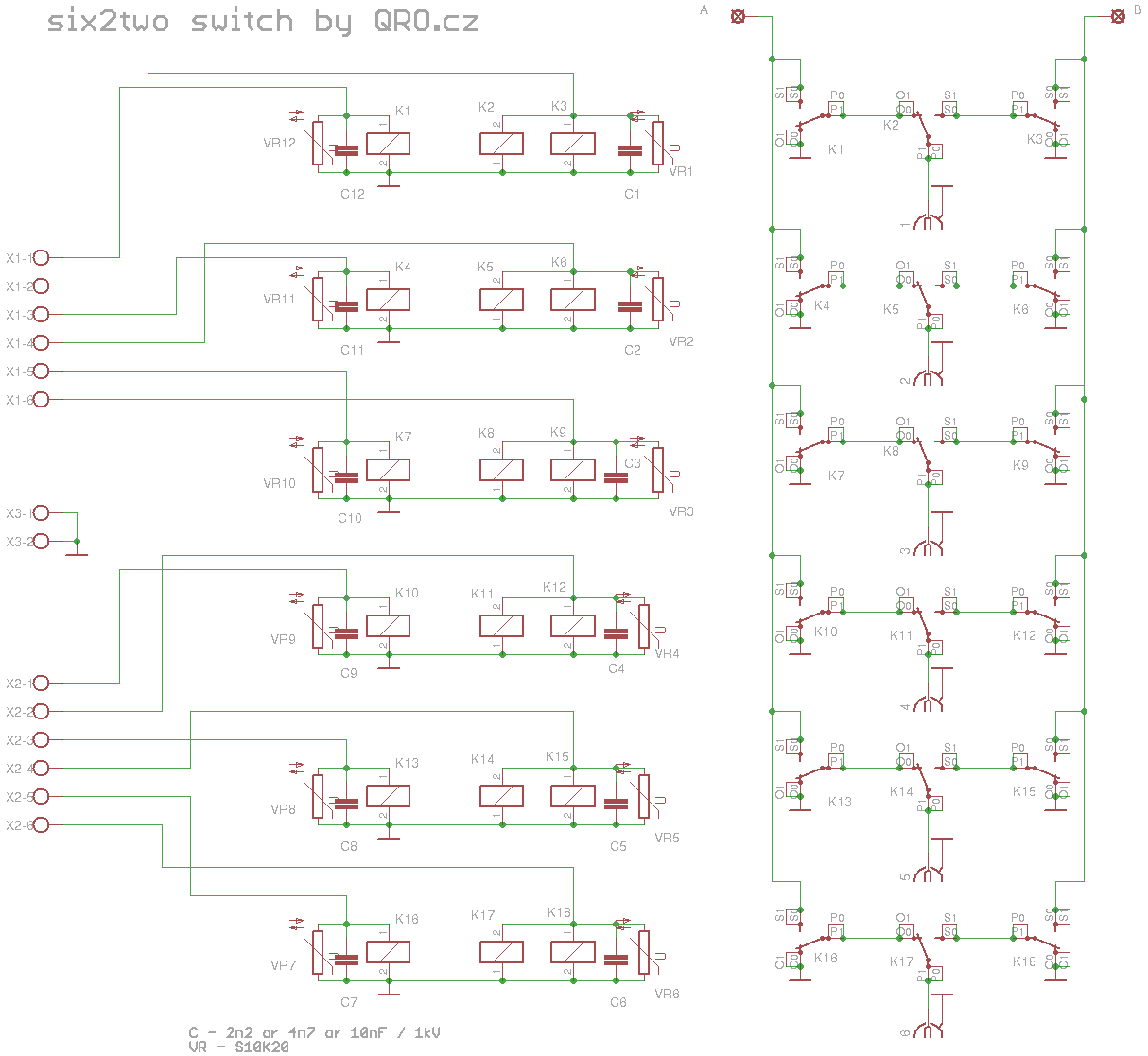 |
|||
| interlock (FiFo) version 3 | pcb  |
sch 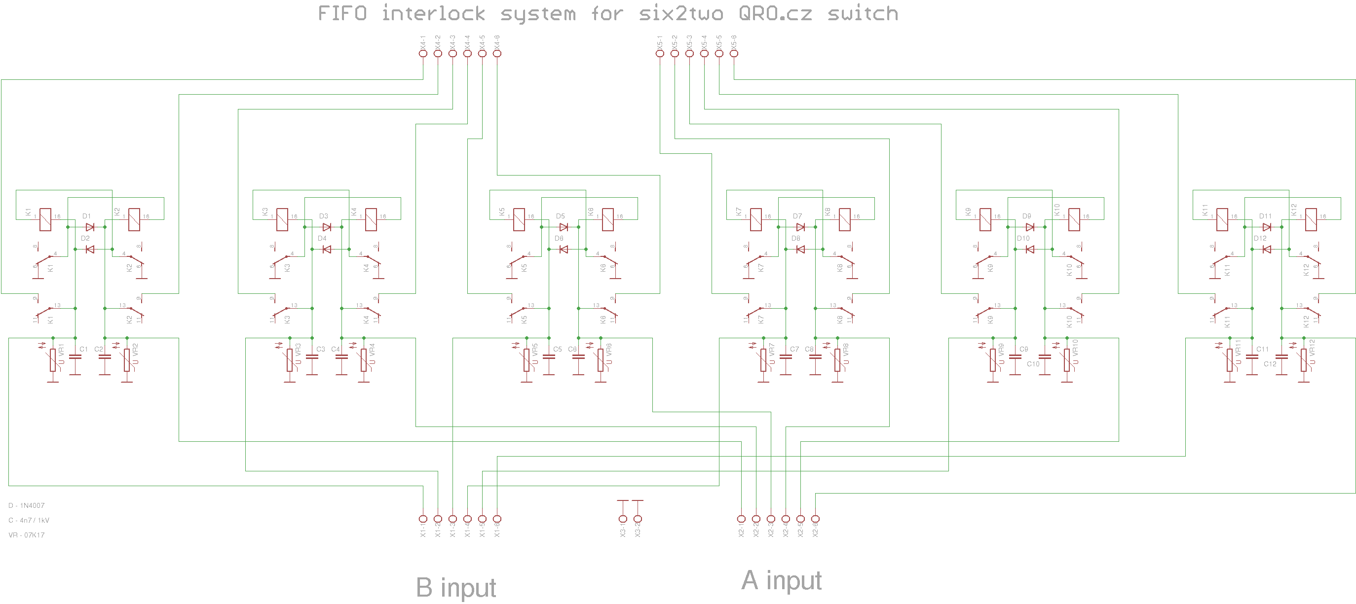 |
|||

|
|||||
|
We believe open source is a better way of doing things. View and download the Shield Schematic and PCB Kicad/Eagle CAD files, LibreCAD .DXF, or Inkscape .SVG files. The hardware designs are released under the Attribution-NonCommercial 2.0 Generic |
|||||
Users implementation
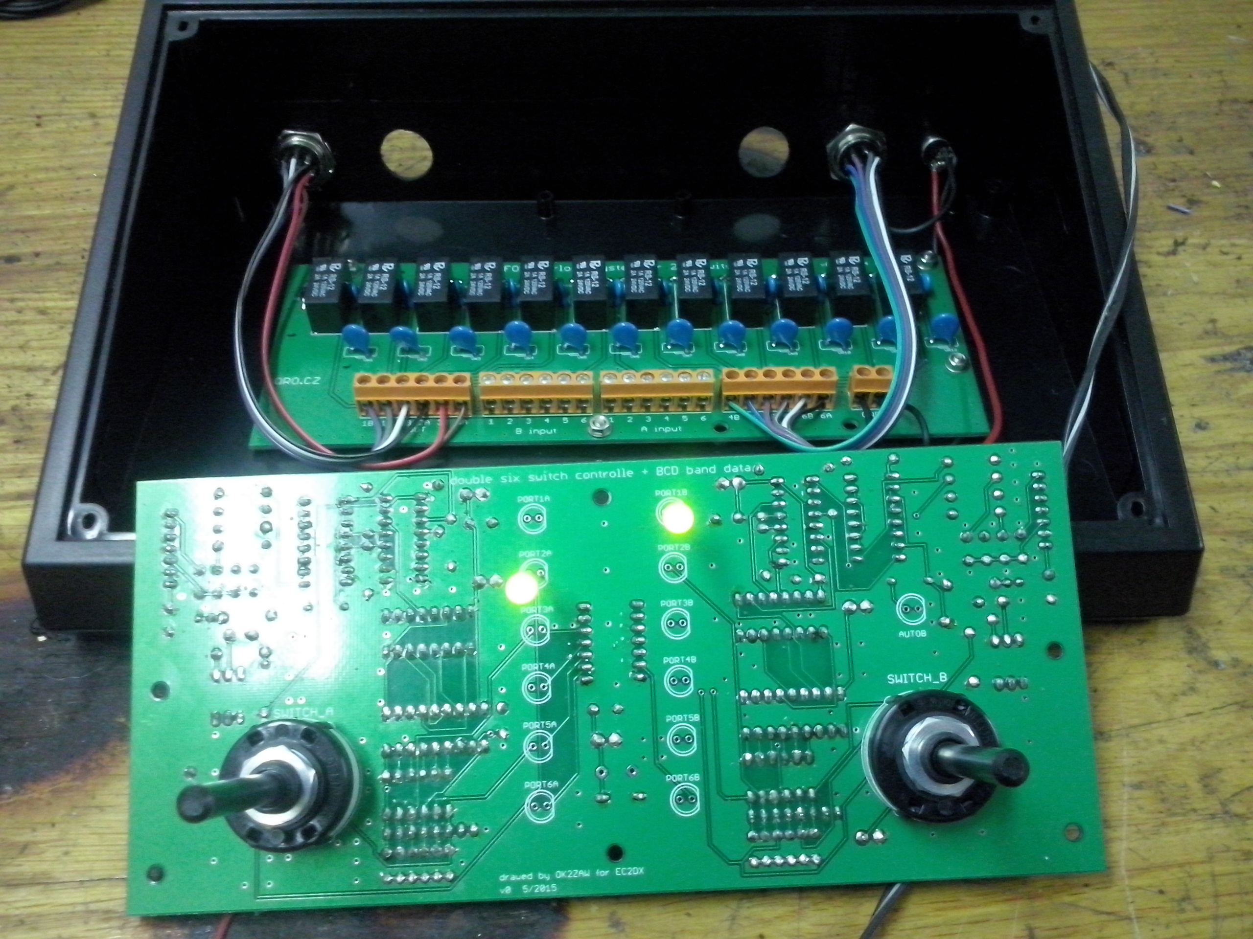 EC2DX |
 EC2DX |
 EC2DX |
 EC2DX |
 EC2DX |
 EC2DX |
 OK1VJ |
 OK1VJ |
 OK1VJ |
 OK1VJ |
Third party software
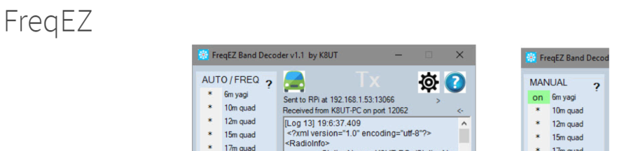
by Larry K8UT, WEB page here
FreqEZ is a Do-It-Yourself hardware/software project that provides highly configurable Band Decoding and Remote Antenna Selection. For amateurs who use N1MM+ and DXLab logging software, FreqEZ will leverage those programs TCP/UDP broadcasts for antenna switching. For other amateurs, FreqEZ can connect to the BCD band outputs available from most transceivers. The FreqEZ software and is freely available to all hams, and consists of a pair of programs that run on the Windows and Raspberry Pi Raspbian operating systems. Watch a short (5 minutes) FreqEZ Overview video HERE


