


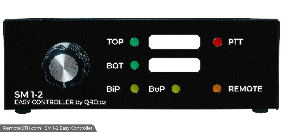
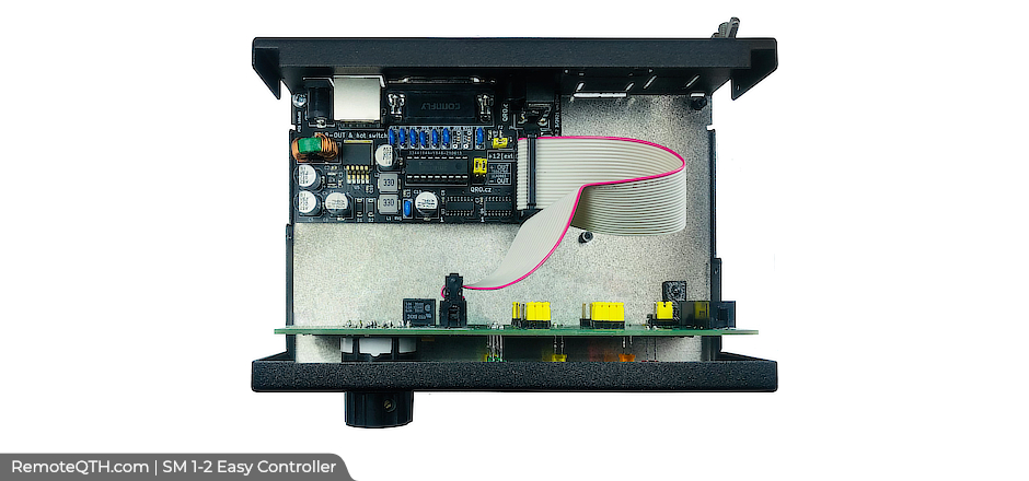
Easy Controller for Stack Match 1-2


This is universal manual and remote (web, IP, cluster) controller for 1 to 2 antennas stack match with Both In / Both Out PHASE. You can use any RF SM (our or your own) and configure jumpers on front panel for all combinations as you need. There is universal output driver - you can use +12 V OUT or switching to the Ground. IP remote module (IMPERO32) is optional. It offers you another 8 external outputs for another relays - you can switch ON PA, light, TRX etc. Output is again universal (+12V or GND). Controller has also PTT hot switch protection.
Main functions:
- Universal controller for stack match 1-2 with BiP/BoP
- All combinations for 2 antennas
- Universal for any stack match with 4 control wires
- All outputs are universal +12V or GND
- HOT switch PTT protection
- IP module with 8 external relays for custom use
- IP/web remote module as option version REMOTE
Parameters:
- Output is universal +12V or + EXT or to GND
- Output current max. 500mA per output, 500mA total
- Output voltage the same as supply voltage or EXT max 26V DC
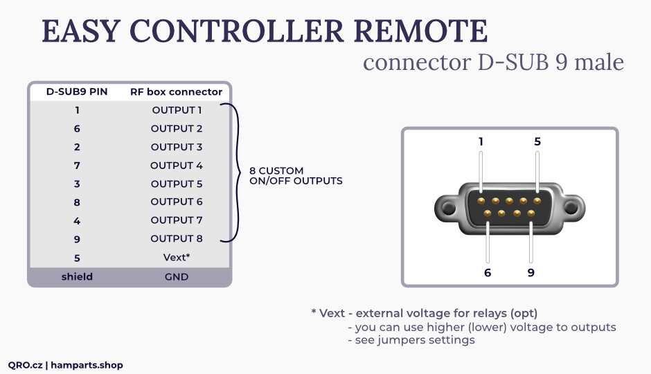
- EXTernal voltage for relays with different voltage than 12V
- Voltage drop for TBD driver typ. 0,2V for +12V input and 0,7V including fuse
- Voltage drop for ULN driver typ. 0,8V for +12V input
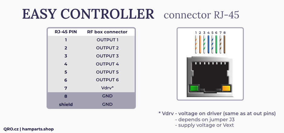
- PTT hot switch protection active to GND (5V logic compatible) picture
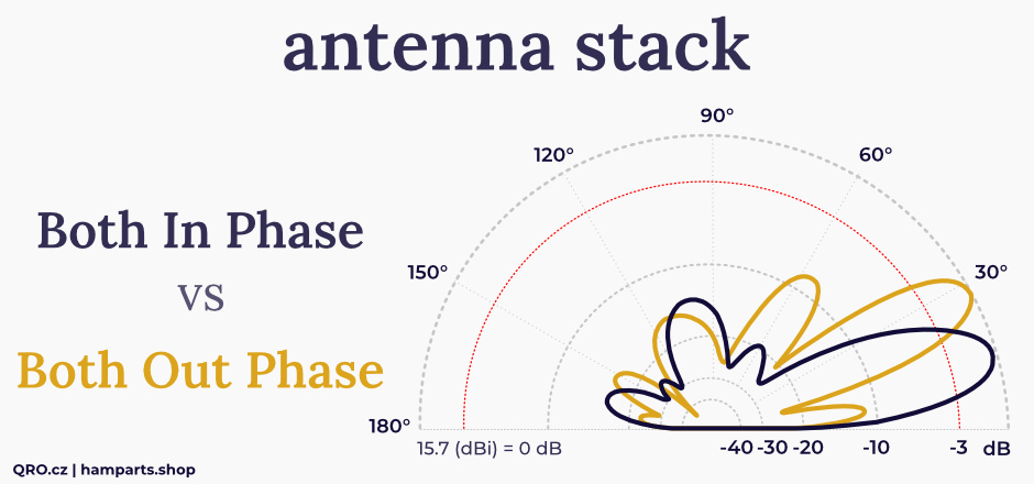
Both-In-Phase vs Both-Out-of-Phase:
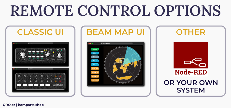
Version with REMOTE control:
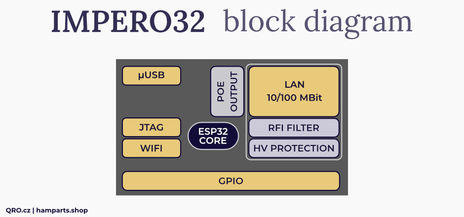
Remote module:
- Control your Antenna switch and external 8 outputs with your browser/http
- Web based application with automated updates
- No configuration or firmware upload needed
- Custom button labels by parameter
- Customize your UI or use our control view
- Can be controlled by stream deck and touchportal
- System is part of our station automation infrastructure by DM5XX's RemoteSwitch.de system
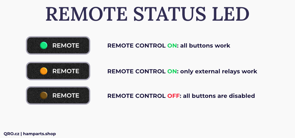
- Remote Control disables front panel switch
- Additional external 8 OUTPUTS - ON/OFF for switching other devices or antennas
- External switching: Universal output driver output +12V or GND
- LAN connection with unique RFI filtering + HV protection
- We recommend a VPN while using remote access from outside your network in general
Parameters for Remote Module / Daughter board OLI IP:
- LAN 10/100 Mbit auto
- ONLY DHCP IP address - not static
- LAN High Voltage double protection
- LAN Common-mode filter = lower RFI emission from LAN cable
- Output is universal +12V or + EXT or to GND
- Output current max. 500mA per output, 500mA total
- Output voltage the same as supply voltage or EXT max 26V DC
- EXTernal voltage for relays with different voltage than 12V
- Voltage drop for TBD driver typ. 0,2V for +12V input and 0,7V including fuse
- Voltage drop for ULN driver typ. 0,8V for +12V input
- EXTERNAL 8 outputs for custom use
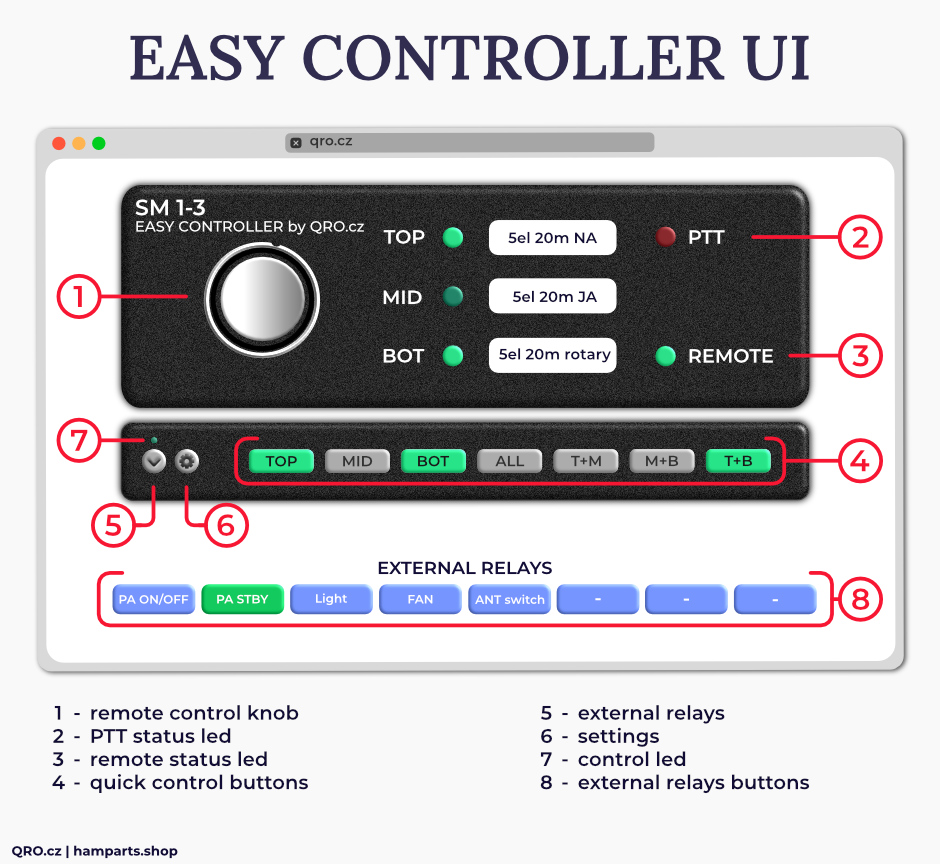
Example for remote control User Interface (UI), there for Stack Match 1-3 controller
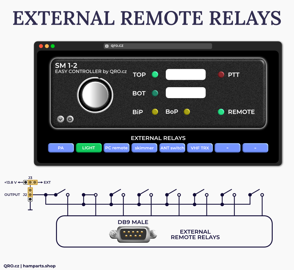
Example for External Relays:
 |
Optional 8 Relay DIN module:
 |
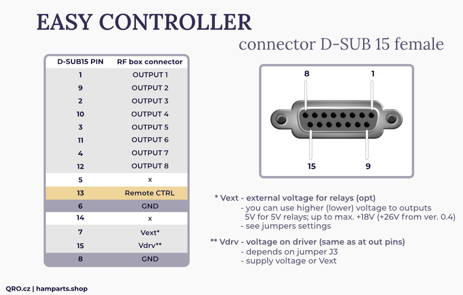
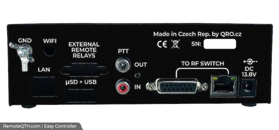
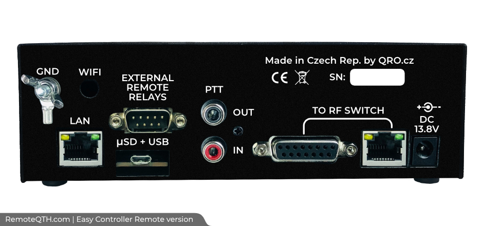
Connectors describtion:
Controller to RF switch:
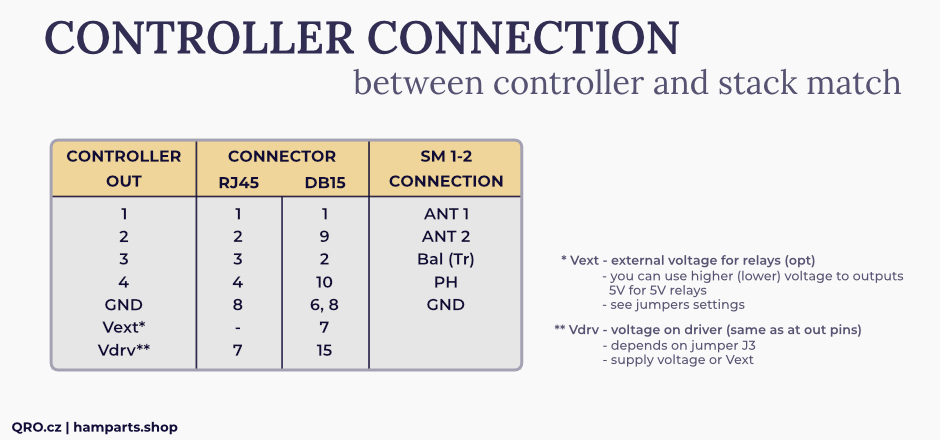
DB15 at controller (only first 4 outputs are used):
RJ45 (TO RF SWITCH) at controller (only first 4 outputs are used):
Remote version DB9 (EXTERNAL REMOTE RELAYS) - external 8 outputs:

Download
| Easy Controller SM 1-3 | ||||
|---|---|---|---|---|
| Front panel 0.4 | sch  |
pcb front 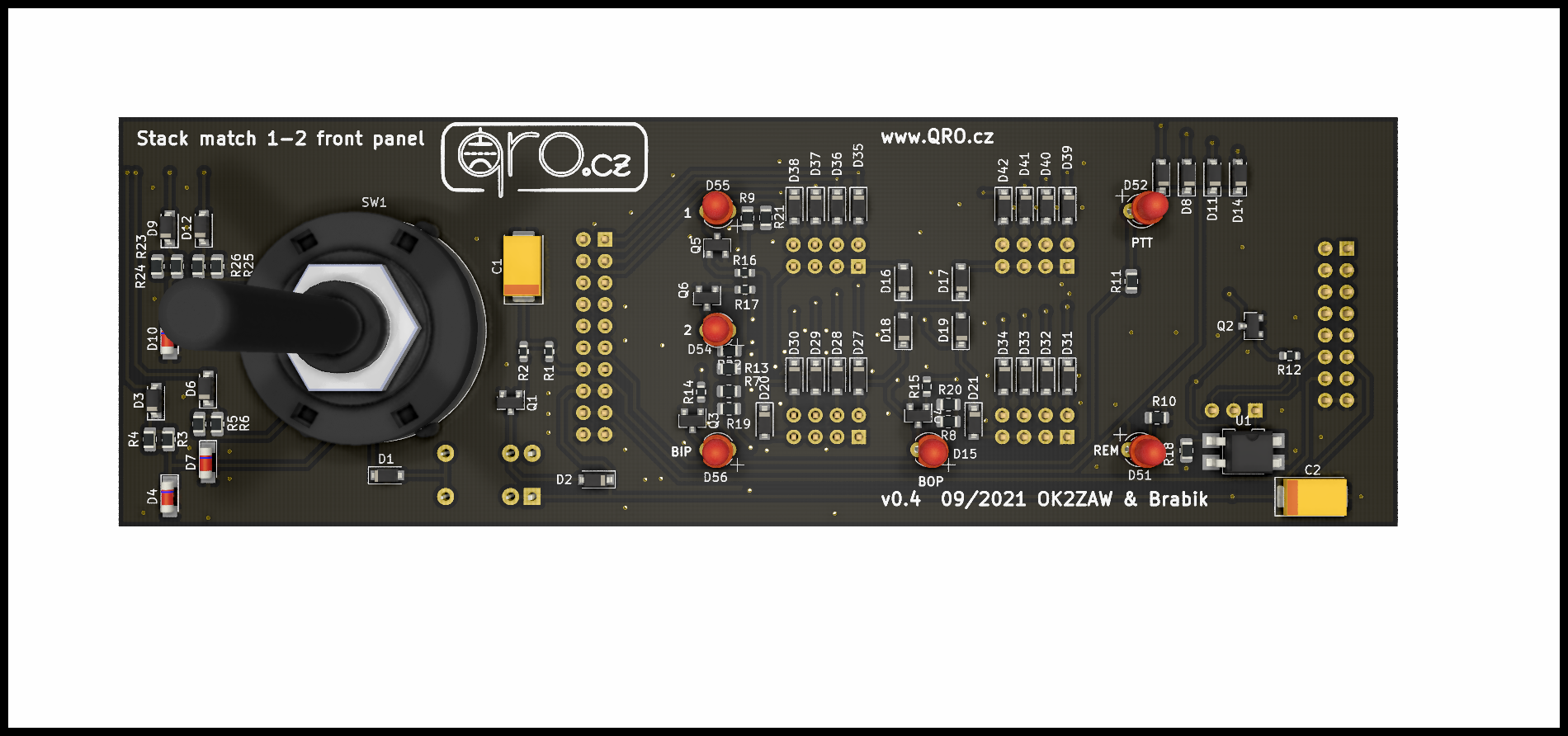 |
pcb rear 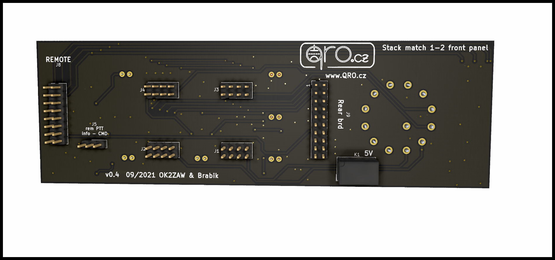 |
|
| Universal 8 OUT board | sch |
pcb  |
828 | |

|
||||
|
We believe open source is a better way of doing things. View and download the Shield Schematic and PCB Kicad/Eagle CAD files, LibreCAD .DXF, or Inkscape .SVG files. Please, do not steal our designs for your commercial use! The hardware designs are released under the Attribution-NonCommercial 2.0 Generic |
||||
Related products:
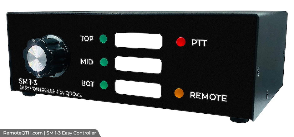 Easy Controller for 1-3 stack match |
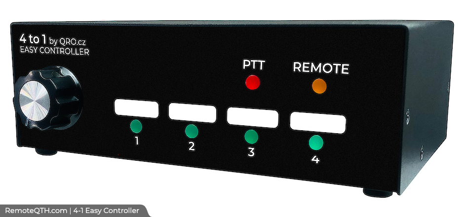 Easy Controller for 4 antennas |
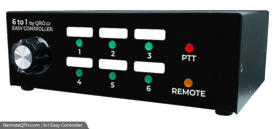 Easy Controller for 6 antennas |
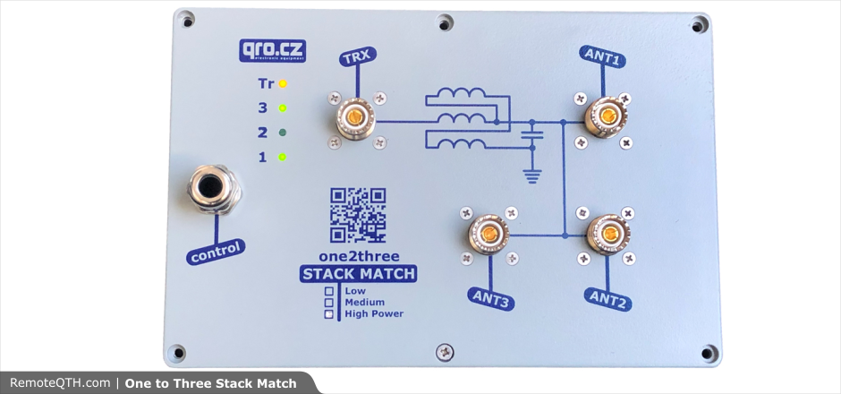
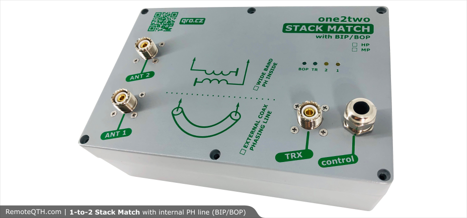 Stack Match 1-2 |
 Stack Match 1-3 |
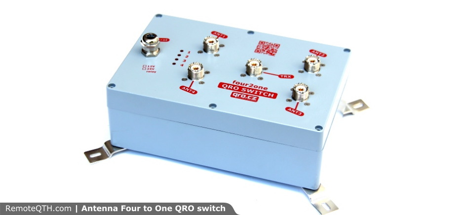 4-to-1 antenna switch |


