


12x4 modular Antenna switch KIT - scalable on your terms
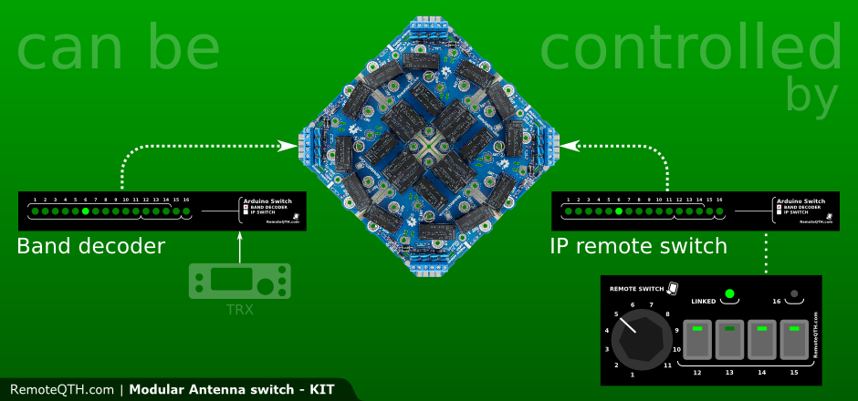
Can be controlled by:


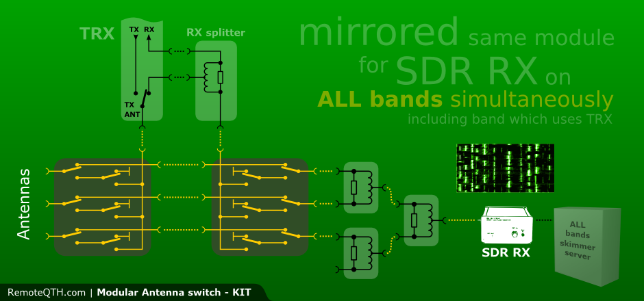
Main functions:
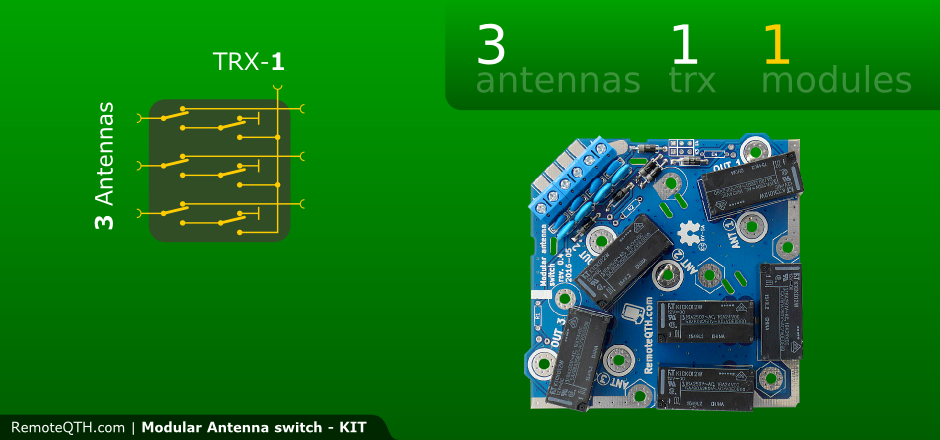
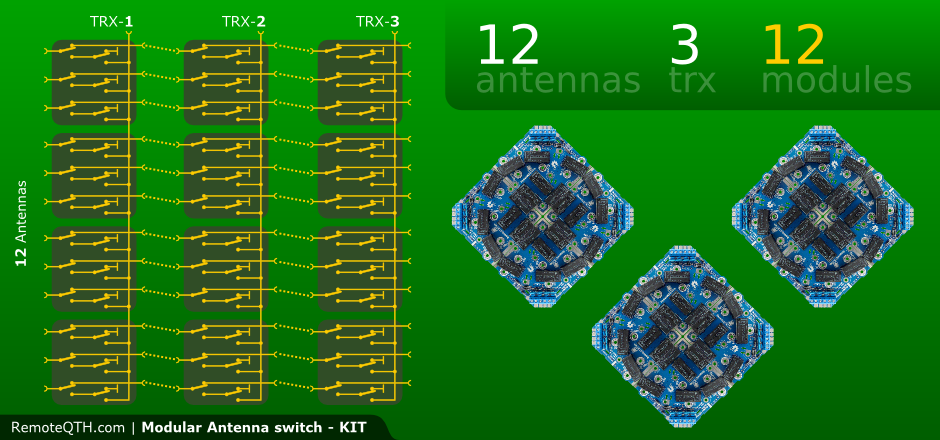
- Always used one same - three to one - module.
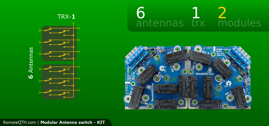
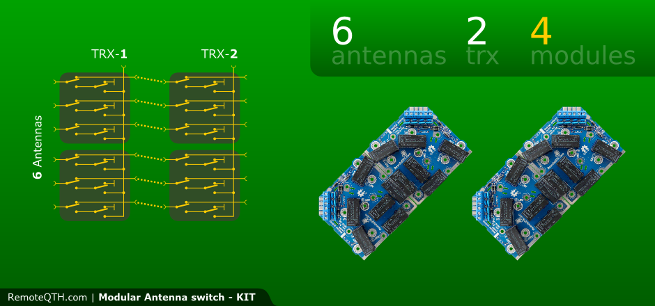
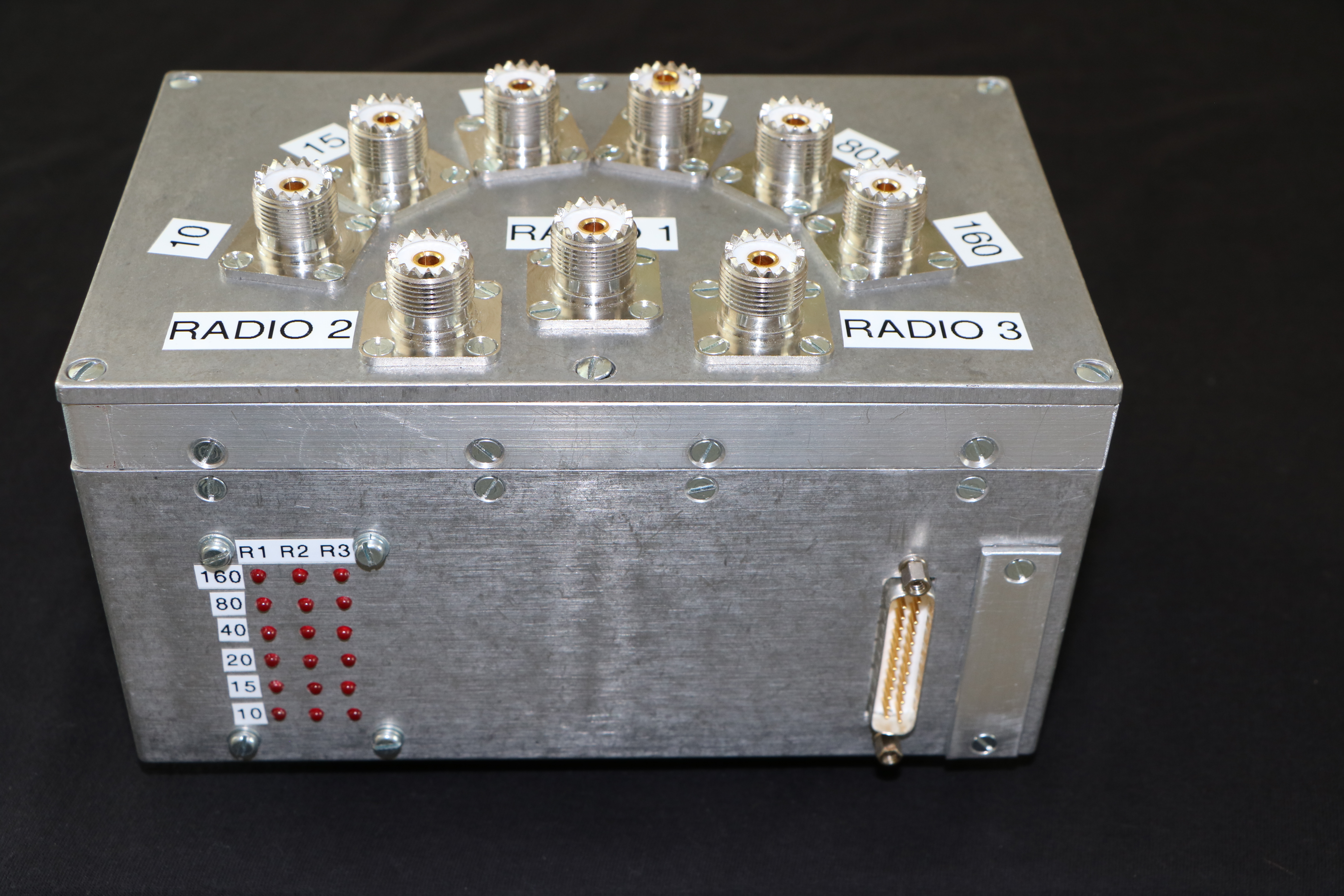
- Put together up to four module expand up to 12 inputs.
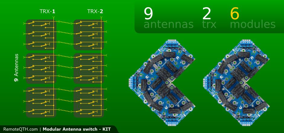
- Available add same module to next layer for next outputs (more second outputs).
- Additionally expandable at a later time.
- Using antenna output shows the LEDs.
- Controled by grounded input (default), or high polarity (if soldered reverse all diode).
- Power voltage 12V typicaly, dependency to used relay.
- One module PCB size 85x85mm.
- RF power loading
- 8A default PCB current (2,7 mm x 1oz)
- >16A with additional wire soldering
- 16A switching current
 Schematics rev 0.4 |
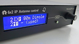
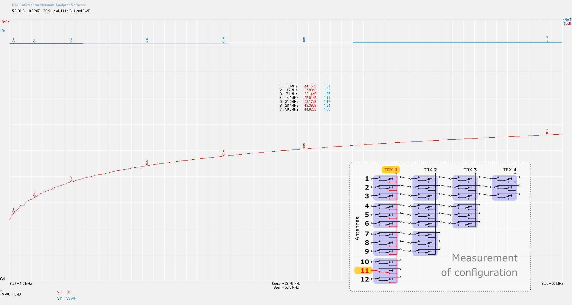
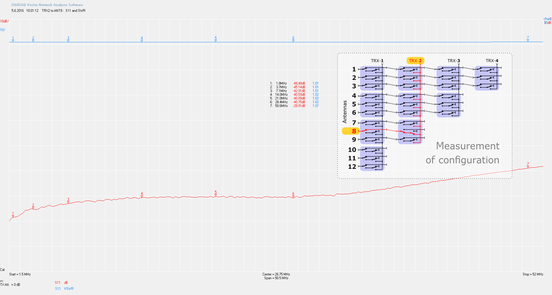
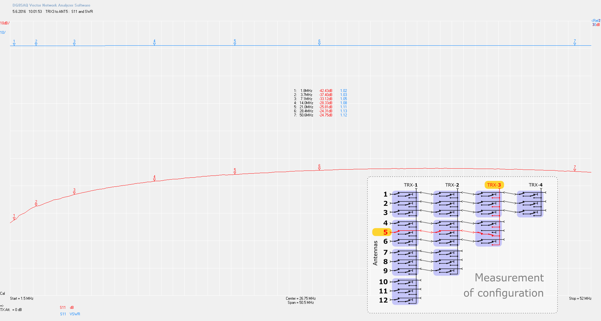
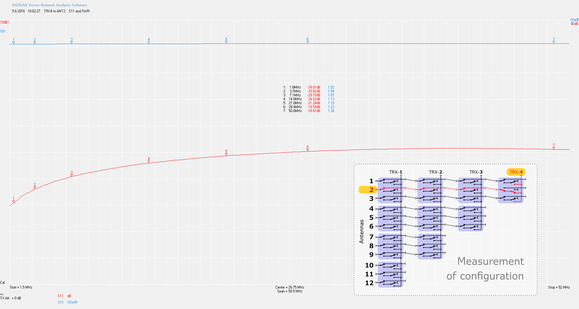
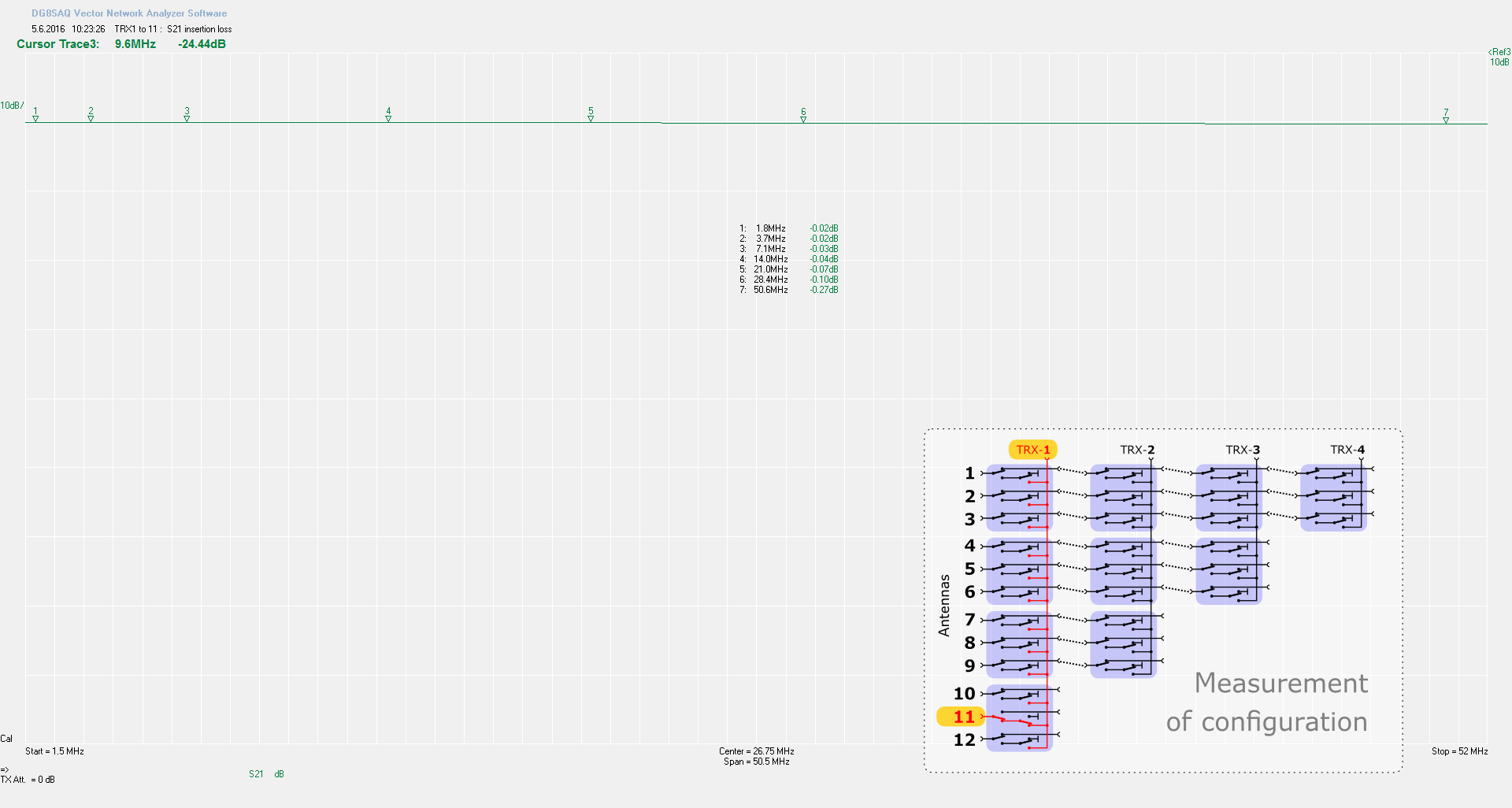
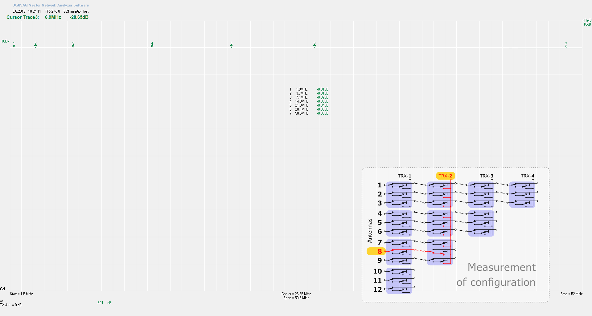
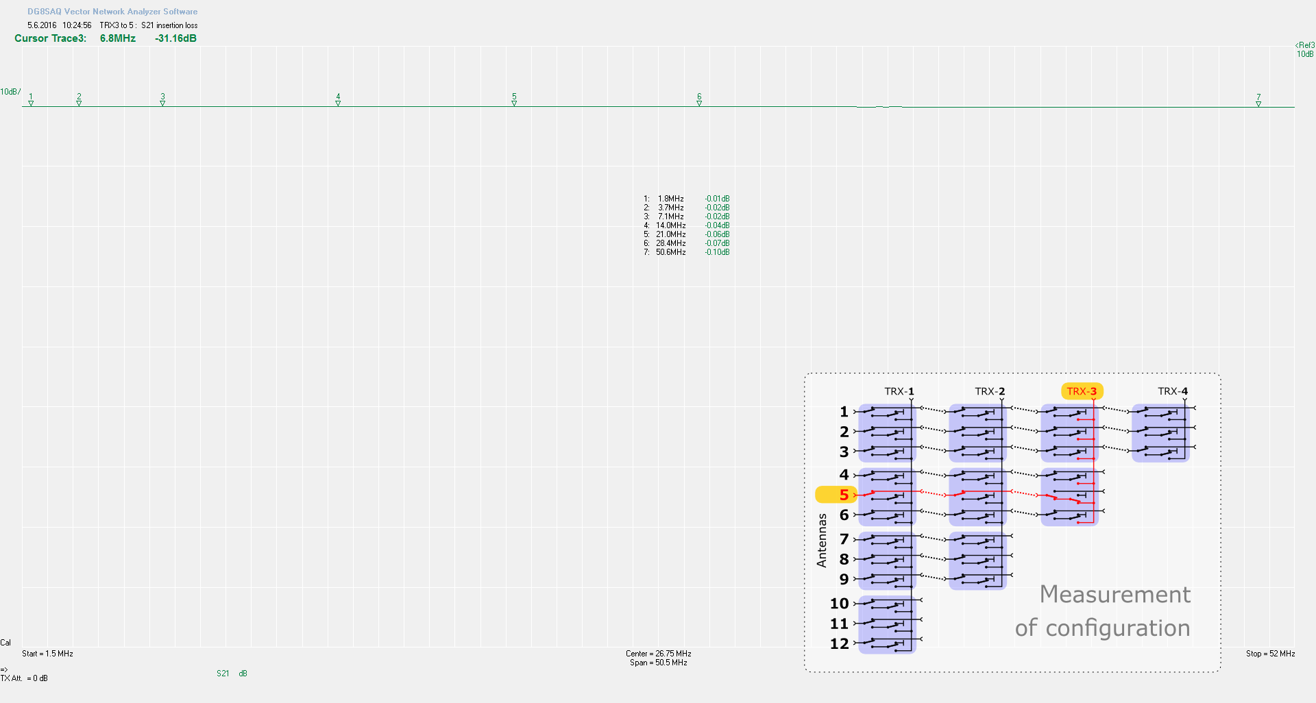
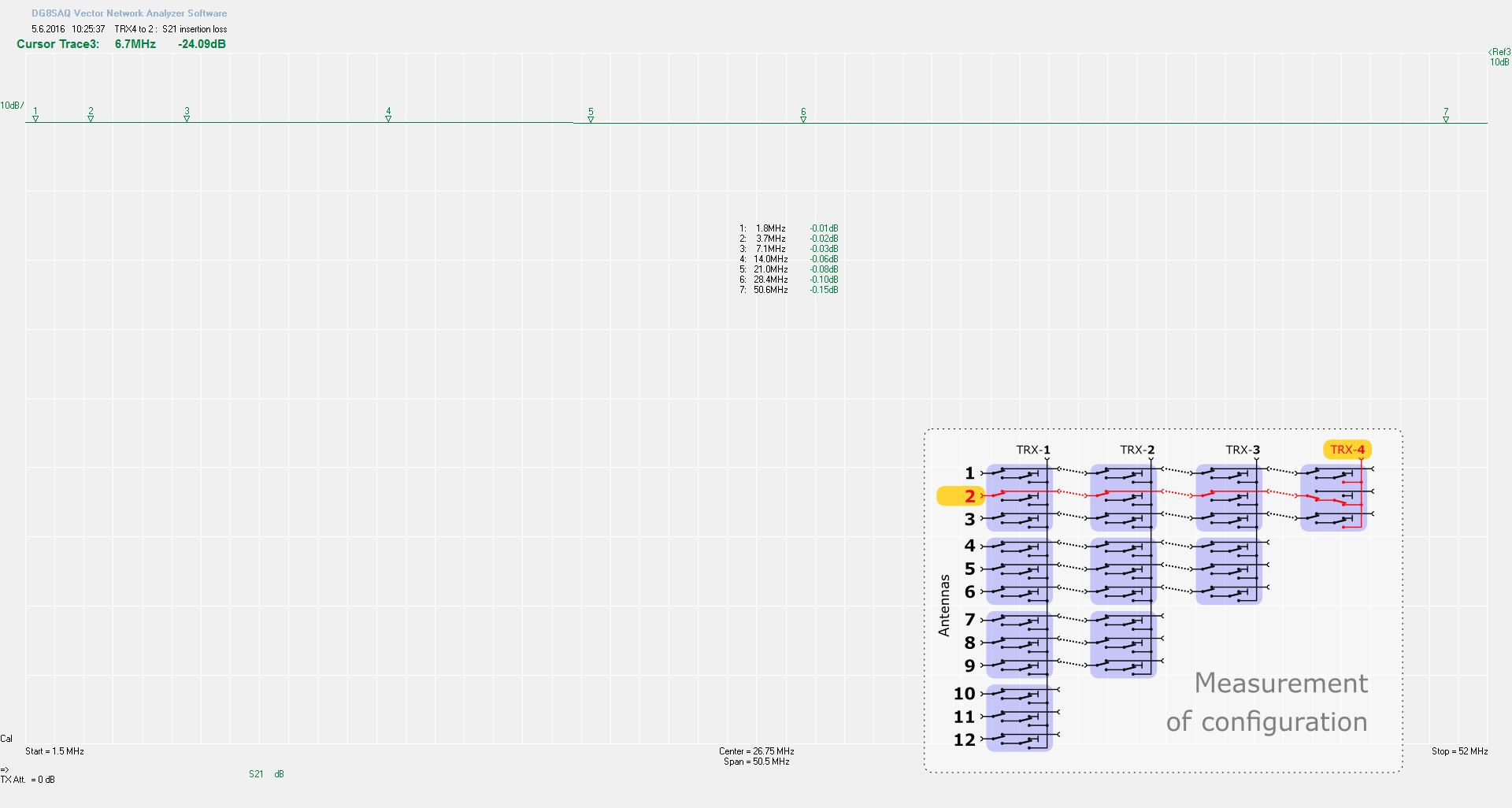
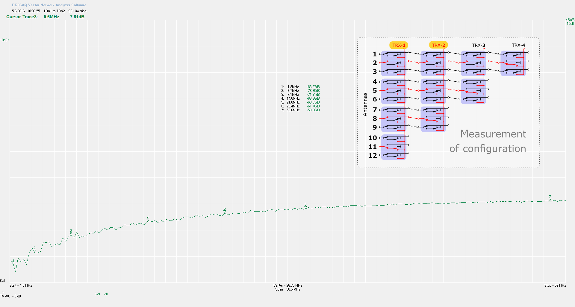
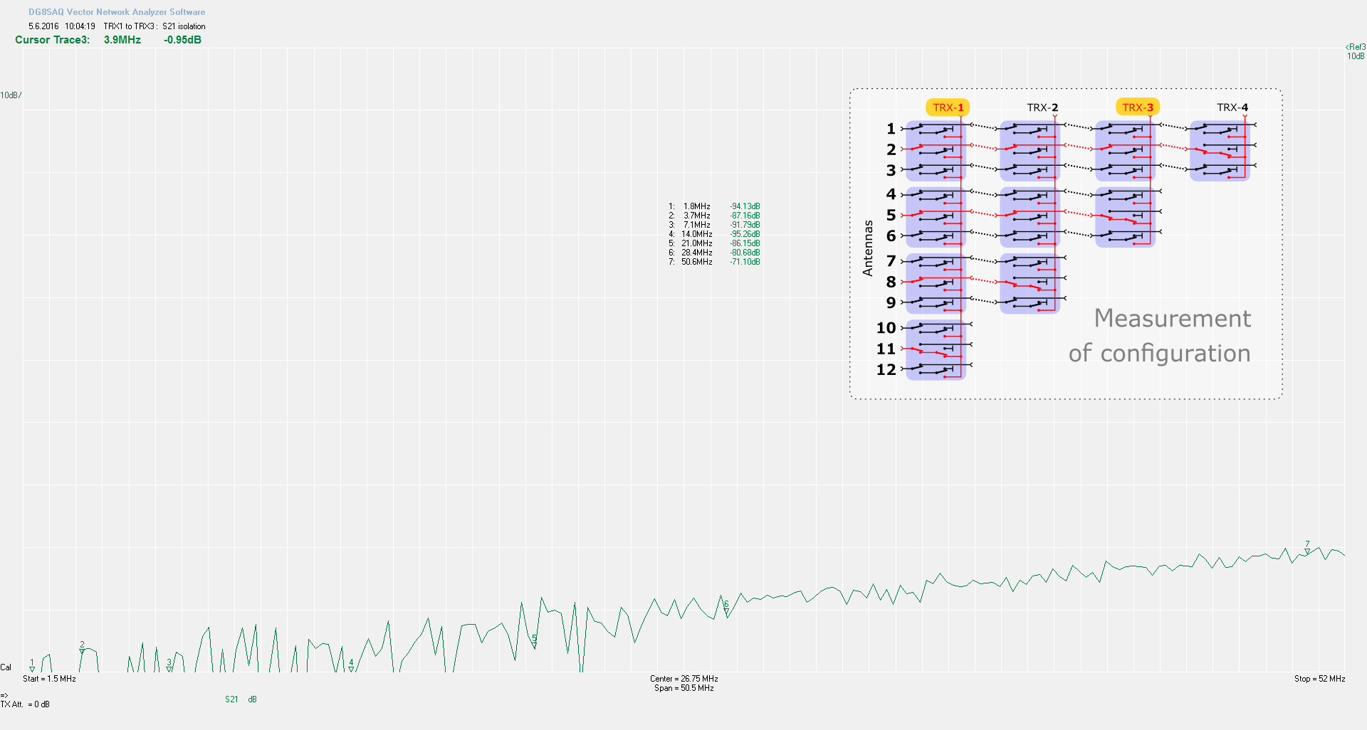
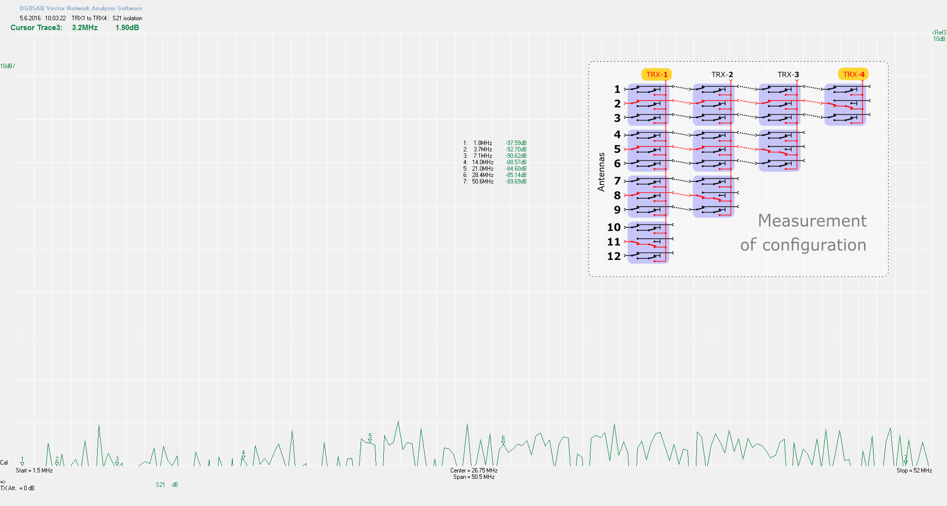
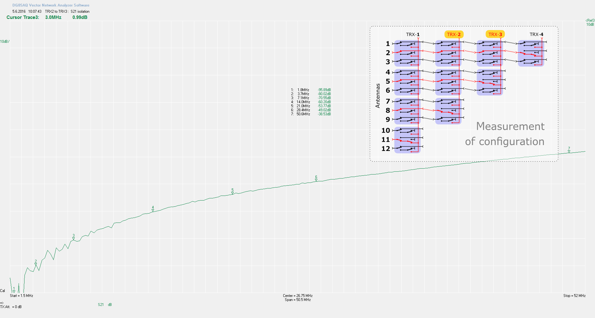
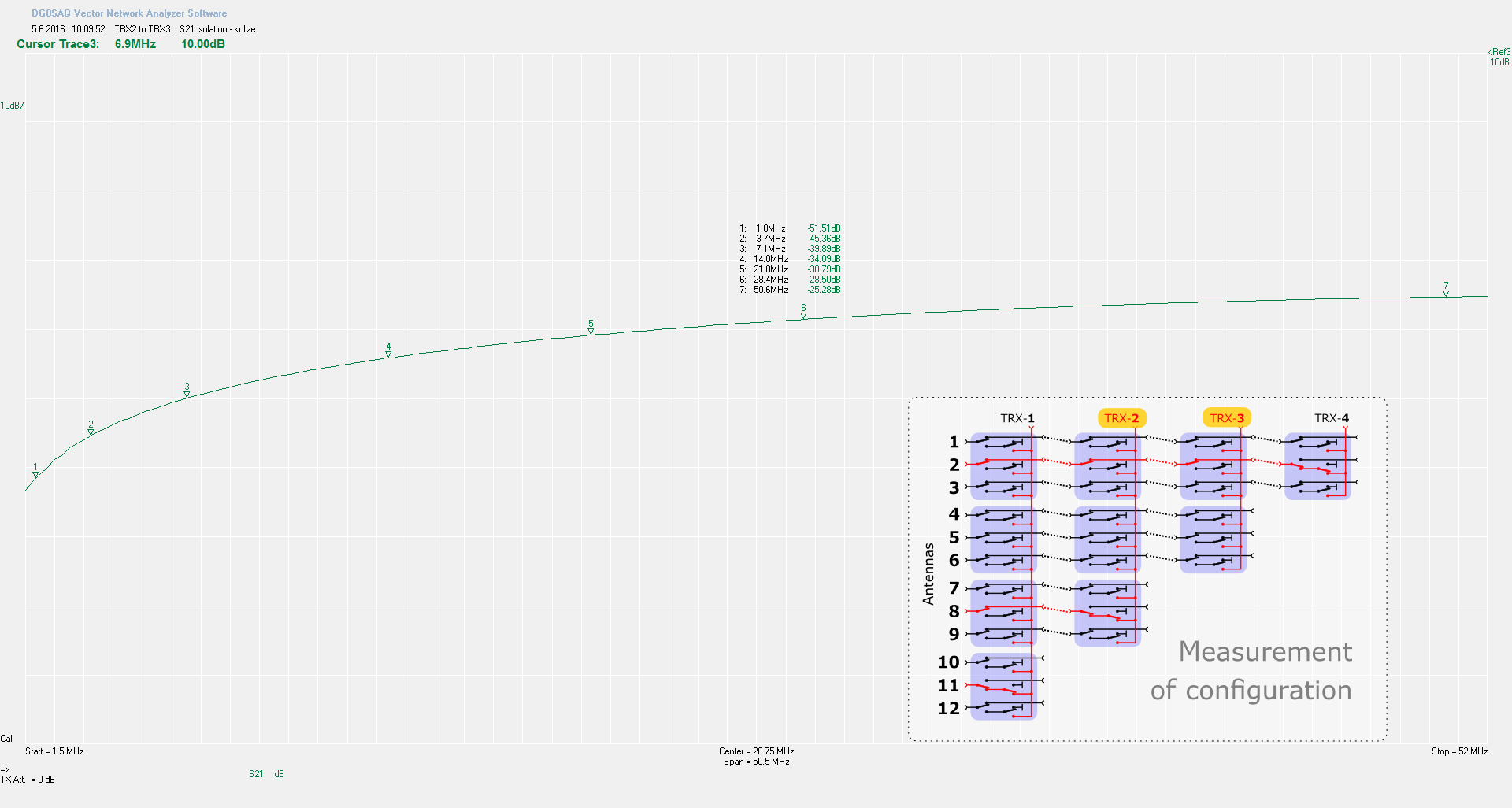
Measured values for several configuration
New switch configurator
| Select | ||||||||||||||||||||||||||||||||||||||||||||||||||||||||||||||||||||||||||||||||||||||||||||||||
|
|
||||||||||||||||||||||||||||||||||||||||||||||||||||||||||||||||||||||||||||||||||||||||||||||||
Download
| PCB | |||
|---|---|---|---|
| rev 0.5 | sch  |
kicad968 | |
| rev 0.4 | pcb-t 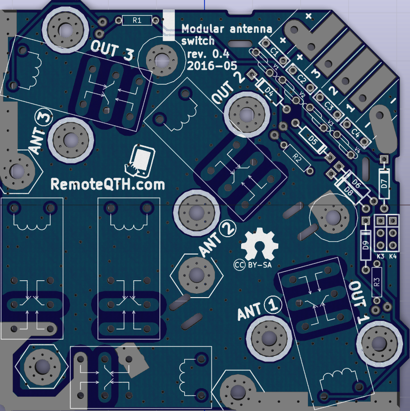 |
pcb-b 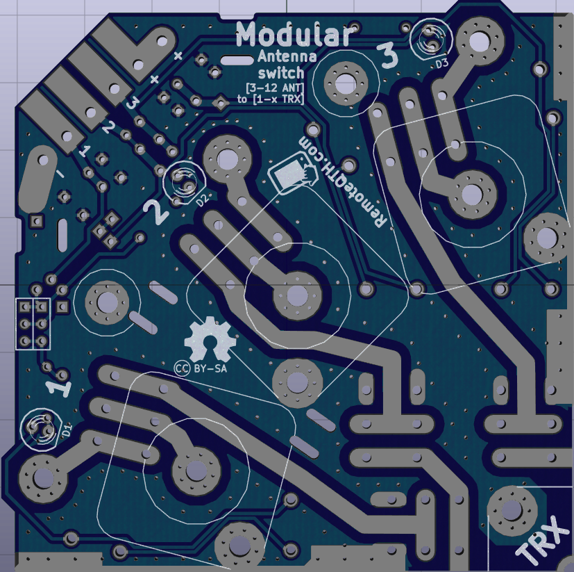 |
 pcb 3D [8,5MB] |
| sch |
kicad968 | ||
| Enclosure | |||
| DXF | front1441 | 2TRX-rear1406 | 4TRX-rear1488 |
| front1382 | sticker1410 | ||
| OK1CDJ 3x1 mini box |
front.dxf1532 | rear.dxf1424 | .scad1532 |
| 3D-print | |||
| Closure unused hole | 1.STL1397 | 3.STL1314 | 3D preview |
 Open-Hardware Open-Hardware
|

|
||
|
We believe open source is a better way of doing things. View and download the Shield Schematic and PCB Kicad/Eagle CAD files, LibreCAD .DXF, or Inkscape .SVG files. The hardware designs are released under the Creative Commons Attribution-ShareAlike 4.0 International License |
|||
Users implementation photos
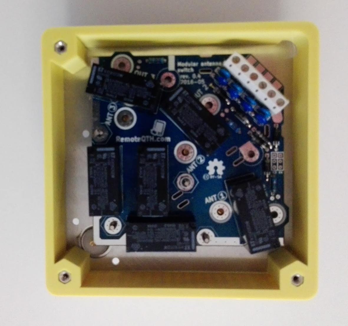 3x1 switch OK1CDJ |
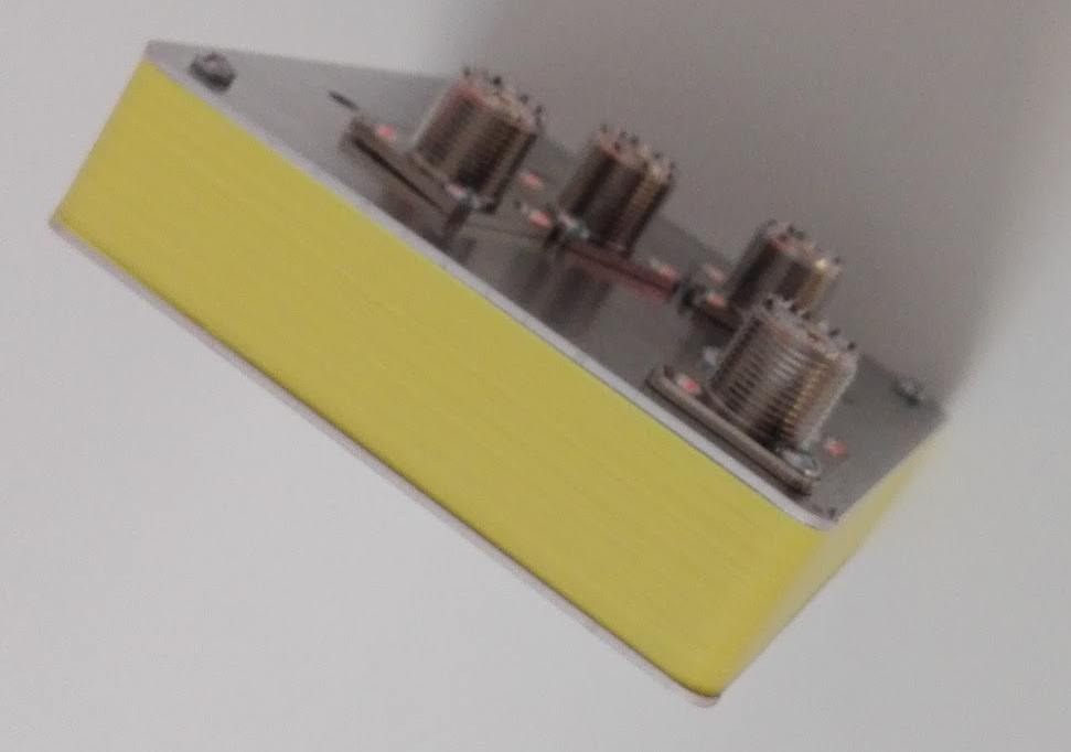 3x1 switch OK1CDJ |
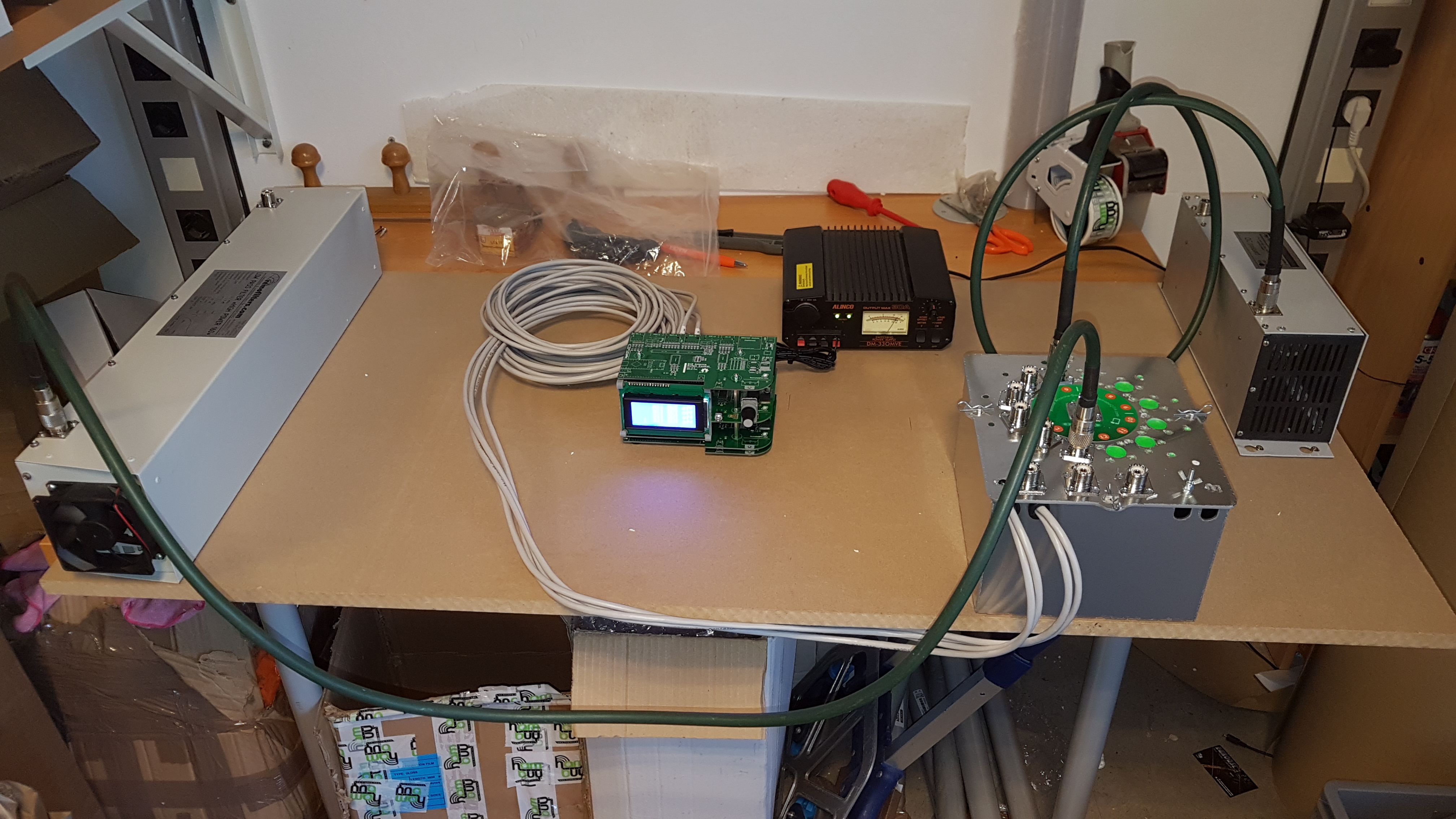 6x4 controller and switch EC5AN |
 6x3 switch G4BVY |
 |
 |
 |